Diesel engine fuel system
The fuel system of a diesel engine uses high pressure fuel (light oil) to inject it into the combustion chamber. As shown in Fig. 1, a fuel tank that stores fuel, a fuel feed pump that supplies the fuel in the tank to the injection pump, A fuel filter that removes impurities and foreign substances contained in the fuel, an injection pump that makes the fuel high pressure and pumps the appropriate amount at the optimum time, an injection nozzle that injects high pressure fuel into the combustion chamber, and a pipe that connects them. It is composed of fuel and fuel.
In addition, for the purpose of separating the water content in the fuel, there are some that are provided with a fuel sedimenter (water separator) between the fuel tank and the fuel feed pump, and some that are provided at the bottom of the fuel filter. ..
The fuel in the fuel tank flows as shown by the arrow in Fig. 1, and the excess fuel is returned to the fuel tank via the return pipe.
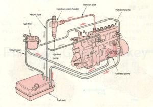
Figure 1: Fuel system
The injection pumps include a row-type injection pump as shown in FIG. 2, which has the same number of plungers as the number of engine cylinders, and a distribution-type injection pump as shown in FIG. 3, which supplies fuel to each cylinder with one plunger. ..
In addition, there is an electronically controlled injection pump that controls the injection amount and injection timing using a control unit.
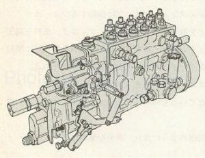
Figure 2: Row injection pump
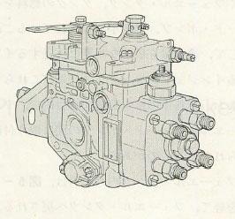
Figure 3: Distributive injection pump
Table of Contents
- Row type injection pump
- Row type injection pump body
- Plunger block assembly
- Camshaft and tappet
- Governor (governor)
- Timer (advance device)
- Fuel feed pump
Row type injection pump
The row-type injection pump is composed of a pump body, a governor, a timer, a fuel feed pump, etc., and is a P-type injection pump as shown in (1) of Fig. 4 (hereinafter referred to as P-type) and (2). There is a type A injection pump. (Hereafter referred to as type A)
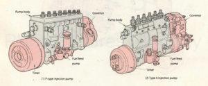
Figure 4: Row-type injection pump
Since the P type is used for engines with a large injection amount equipped with a direct spray combustion chamber for medium and large vehicles that carry heavy objects, the pump body is completely sealed, high pressure resistant and completely sealed. It has a structure with excellent high pressure resistance and oil tightness resistance.
The A type is used for engines with a relatively small amount of spray, equipped with a vortex chamber type combustion chamber of a small car that does not require the transportation of heavy objects, so the pump body is open and the structure is as robust as the P type. do not need.
This time, we will explain the P-type row-type injection pump used in general medium-sized vehicles and large-sized vehicles.
Row type injection pump body
As shown in Fig. 5 (1), the pump body has a pump housing that forms the framework of the pump, a camshaft and tappet for driving the plunger, a plunger that weighs and pressurizes the fuel, and improves the cutoff of the injection. It consists of a delivery valve that prevents backflow and a control unit that controls the increase and decrease of fuel.
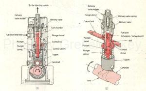
Figure 5: Pump body
The camshaft is driven by the drive shaft or gears of the engine, and its rotational speed is half that of the engine body.
When the camshaft rotates, the cam causes the central plunger to slide up and down in the plunger barrel via the tappet to pump fuel. (Piston movement)
When the plunger is lowered, the fuel in the fuel chamber is sucked into the barrel, and when the plunger is raised, the delivery valve is pushed open and pumped to the injection nozzle.
The control rod moves in conjunction with the accelerator pedal or governor, and this movement is transmitted to the control sleeve via the ball to rotate the plunger.
Since the amount of fuel supplied to the injection nozzle changes depending on the position where the plunger rotates, the amount of fuel supplied is increased or decreased by this mechanism.
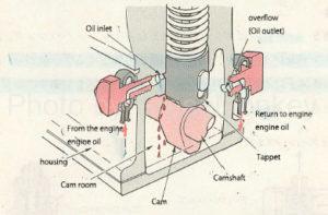
Figure 6: Oil supply to the cam chamber
On the other hand, the camshaft and tappet are lubricated by supplying a part of the engine oil from the oil inlet to the cam chamber as shown in Fig. 6 and splashing this oil with the cam. A route is created so that it returns from the overflow port (oil outlet) to the oil pan of the engine, and the mechanism is such that this route is constantly circulated.
The plunger and delivery valve are lubricated with fuel (light oil).
Pump housing
The pump housing (the housing that covers the entire pump from the outside) has a fuel chamber that stores fuel sent from the fuel feed pump, a cam chamber that stores lubricating oil sent from the engine, and a plunger block. The assembly, control rod, camshaft, etc. are incorporated.
Plunger block assembly
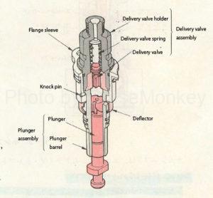
Figure 7: Plunger lock assembly
As shown in FIG. 7, the plunger block assembly is composed of a plunger assembly, a delivery valve assembly, a flange sleeve, a deflector, and the like, and is attached to the pump housing.
Plunger assembly
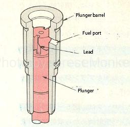
Figure 8: Plunger assembly
As shown in Fig. 8, the plunger assembly consists of a plunger and a barrel, and the plunger moves up and down in the barrel to pressurize the fuel to 17-23Mpa.
The sliding part between the plunger and the barrel is ground with high precision to maintain oil tightness. Grinding is done by applying a wrapping agent (abrasive) and moving the plunger up and down while rotating it. The parts that have been ground are used in combination with other parts. should not be done.
Therefore, when exchanging, the plunger and barrel are set.
- Plunger operation
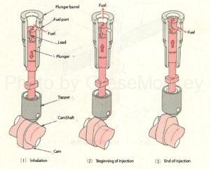
Figure 9: Plunger operation
Fig. 9 shows the operation of the plunger. When the plunger descends as shown in Fig. 9 (1) and the fuel port (intake / discharge port) where the upper end surface is exposed is opened, the plunger enters the barrel from the fuel chamber. Fuel is inhaled.
Next, as shown in Fig. 9 (2), when the plunger rises from the bottom dead center due to the rotation of the cam and the upper end surface closes the fuel port, pressurization in the barrel starts, and when a certain pressure is reached, The delivery valve opens due to the pressure of the fuel, and the pumping of the fuel to the injection nozzle begins.
Furthermore, when the plunger rises and the plunger lead (notch) leads to the fuel port, the fuel is returned to the fuel chamber as surplus fuel from the lead via the fuel port as shown in Fig. 9 (3). Then, the pumping of fuel is completed.
The plunger rises to the top dead center position by the cam even after the fuel injection is completed, but the fuel is not pumped during this period.
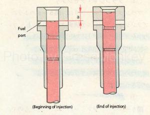
Figure 10: Effective stroke of the plunger
Of the ascending stroke from the bottom dead center to the top dead center of the plunger, the period during which the plunger is pumping fuel is called the effective stroke of the plunger.
As shown in FIG. 10, this effective stroke is represented by the distance (a) that the plunger moves during the period from the start of injection to the end of injection.
- Control of injection amount
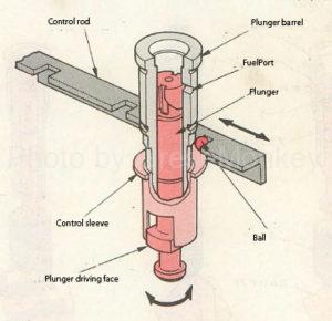
Figure 11: Injection amount control mechanism
As shown in Fig. 11, the driving face of the plunger is fitted into the notch of the control sleeve (the brim part), so the control rod moves from the ball through the control sleeve to increase or decrease the injection amount. By turning the plunger, the effective stroke of the plunger changes, and the injection amount is increased or decreased.
Further, since the control rod rotates the plungers for each cylinder of the engine body by the same amount at the same time, the injection amount to all the cylinders is controlled at the same time.
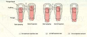
Figure 12: State when the plunger is rotated
FIG. 12 shows the relationship between the effective stroke when the plunger is rotated and the injection amount, and FIG. 12 (1) shows the state of the plunger when the control rod is moved to the position of the maximum injection amount. The effective stroke at is maximized as shown in a in the figure.
Fig. 12 (2) shows the state when the control rod is moved in the direction of reducing the maximum injection amount by half from the state of (1), and the effective stroke according to this movement amount is shown in Fig. 12b. It becomes half of the maximum injection.
In Fig. 12 (3), the effective stroke is zero because the lead part always faces the fuel port even if the plunger is raised at this time when the control rod is moved to the maximum in the direction of reducing the injection amount. , The fuel is in a non-injection amount state.
As a result, it can be understood that the longer the effective stroke of the plunger is, the larger the injection amount is.
- Plunger type
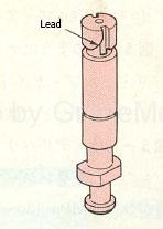
Figure 13: Plunger outer diameter
The plunger has a shape as shown in FIG. 13, and the leads are 180 ° symmetrical and processed in the same shape.
Two barrel fuel ports are also provided to correspond to the shape of the plunger, and the fuel at the top of the plunger after injection is quickly returned to the fuel chamber.
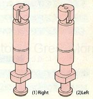
Figure 14: Lead orientation
In addition, since the direction of increase / decrease in the injection amount of the control rod is opposite depending on the governor mounting position (pump engine mounting position), it is necessary to match the direction of the plunger lead, so it is wound left as shown in Fig. 14. A lead and a right-handed lead are provided.
The direction of the reed is such that when the plunger is viewed from the bottom, the injection amount increases when the left-handed one is rotated counterclockwise and the right-handed one is rotated clockwise.
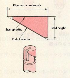
Figure 15: External shape and plan view of the plunger
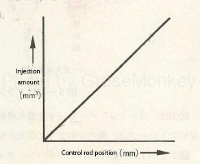
Figure 16: Relationship between control rod position and injection amount
When the lead that determines the effective stroke of the plunger is expanded, it becomes as shown in FIG. 15. Therefore, the injection amount per plunger stroke with respect to the position of the control rod has the injection amount characteristic as shown in FIG. 16 along the notch of the lead. ..
That is, the rate of change in the injection amount corresponding to the change in the position of the control rod is always constant.
Delivery valve assembly
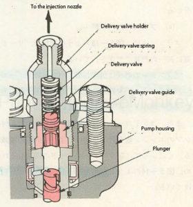
Figure 17: Delivery valve assembly
The delivery valve assembly is attached to the upper part of the plunger with a delivery valve holder, and is composed of a delivery valve, a delivery valve guide, a delivery valve spring, etc. as shown in FIG.
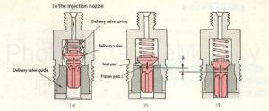
Figure 18: Action of delivery valve
Fig. 18 shows the operation of the delivery valve. When the pressure of the fuel pressurized by the plunger reaches about 3 to 5 MPa, the delivery valve spring is compressed as shown in Fig. 18 (1), and the delivery valve is released. It opens and is pumped to the injection nozzle via the injection pipe.
Next, when the lead of the plunger is passed through the fuel port of the barrel and the oil supply pressure is lowered, the delivery valve is closed by the spring force of the delivery valve as shown in FIG. 18 (3).
At this time, the seat portion of the delivery valve is in close contact with the upper end of the delivery valve guide to prevent the fuel from flowing back when the plunger is lowered, and at the same time, to maintain the residual pressure in the pipe.
However, if this residual pressure is too high, fuel is injected from the injection nozzle even after the injection is completed, which adversely affects the engine performance and exhaust gas.
Therefore, it is necessary to suck back a certain amount of fuel in order to improve the fuel injection cutoff of this injection nozzle. This operation is performed from the state shown in Fig. 18 (2) to the state where the seat part of the delivery valve comes into close contact with the delivery valve guide as shown in Fig. 18 (2) to maintain the residual pressure in the pipe properly. be able to.
The amount of a in FIG. 18 at this time is called the suction stroke amount by the piston portion.
Camshaft and tappet
Camshaft
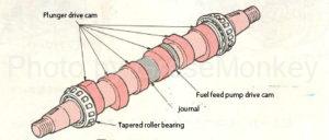
Figure 19: Camshaft
As shown in FIG. 19, the camshaft is provided with a cam for operating the plunger according to the injection order via the tappet and a cam part for driving the fuel feed pump, and a timer and a governor are provided at both ends thereof. Is installed.
Both ends of the camshaft are supported by tapered roller bearings, and the central part is supported by plain bearings by journals.
In the case of an engine with a large number of cylinders, it is necessary to lengthen the camshaft, so some journals have two or more journals.
Tappet assembly
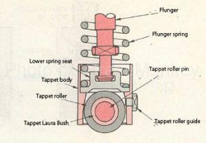
Figure 20: Tappet assembly
As shown in FIG. 20, the tappet assembly is composed of a tappet body, a tappet roller, a tappet roller bush, a lower spring seat, and the like.
The tappet roller has a roller in contact with the cam, and is supported by a roller pin on the tappet body.
Governor (governor)
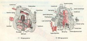
Figure 21: Minimum Maximum Speed Governor
The governor prevents the engine speed from changing significantly when the engine load fluctuates slightly, and also adjusts the engine speed according to the engine load so that the engine does not exceed the maximum speed. The fuel injection amount is automatically controlled.
When the governor is classified in terms of its function, the all-speed governor that controls the entire rotation range and the minimum maximum speed that controls only the idling and the maximum rotation speed and does not perform the speed control action in the middle range.・ There is a governor.
FIG. 21 shows an example of a minimum maximum speed governor. (1) is called a RQ type governor, and (2) is called an RFD type governor.
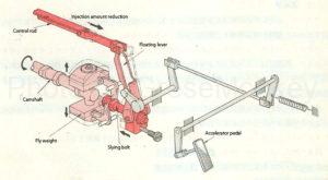
Figure 22: Basic structure of governor
As shown in Fig. 22, the governor floats the link mechanism that moves the control rod of the plunger via the floating lever in conjunction with the accelerator pedal, and the fly weight that rotates with the camshaft of the injection pump and the movement of the fly weight due to the centrifugal force. It consists of two link mechanisms, a link mechanism that transmits to the control rod via a lever.
Principle of governor speed control
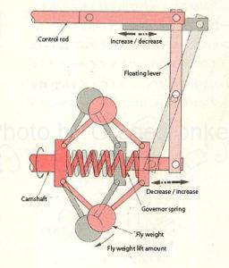
Figure 23: Governor operating principle
Fig. 23 shows the operating principle of the governor’s speed control action. When the engine is rotating at a certain rotation speed, when the engine load decreases and the rotation speed starts to increase due to conditions such as the road, at the same time The rotation speed of the fly weight increases and the centrifugal force increases.
For this reason, the balance with the spring force of the governor spring connected to the governor weight is lost, and the centrifugal force due to rotation acts in the direction of overcoming the spring force of the governor spring (the direction in which the spring is contracted). , The governor weight begins to spread outward.
By this operation, the control rod is pulled in the direction of reducing the injection amount via the floating lever, so that the rotation speed of the engine is maintained at a rotation speed commensurate with the load. (Fig. 23)
In the opposite case, when the engine load increases and the engine speed begins to decrease, the centrifugal force applied to the fly weight becomes smaller, and the force becomes smaller than the spring force of the governor spring, so that the fly weight is inward. Be returned.
As a result, the control rod is pushed in the direction of increasing the injection amount via the floating lever, so that the engine rotation speed is maintained properly again.
Timer (advance device)
The timer is when the engine speed changes. The fuel injection timing is automatically controlled so that the optimum combustion state can be obtained according to the amount of change.
The high-pressure fuel generated by the rise of the plunger is injected from the injection nozzle into the combustion chamber, but in reality, there is a delay in the pressure reaching time to the injection nozzle and a delay in ignition and combustion of the fuel.
This delay increases with respect to the crank angle as the engine speed increases.
Therefore, in order to obtain an appropriate ignition timing, it is necessary to advance the rising time of the plunger, that is, the start time of fuel injection as the rotation speed increases.
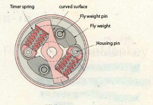
Figure 24: Timer (advance device)
FIG. 24 shows an example of a timer, but the fly weight opens the housing pin to the outside to directly advance the angle.
In this way, the timer functions to adjust the injection timing according to the rotation speed of the engine.
In addition, some timers have a fly weight that rotates an eccentric cam to advance the angle.
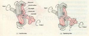
Figure 25: Timer operating principle
FIG. 25 shows the operating principle of the timer. When the engine is lower than the specified rotation speed, the fly weight does not operate because the spring force of the timer spring is larger than the centrifugal force of the fly weight as shown in Fig. 25 (1), and the rotational force from the engine is the drive arm. Is sequentially transmitted to the driven arm and the camshaft via the fly weight, but since the driven arm is in a fixed state with respect to the drive arm, the output side camshaft is not advanced and the injection timing is not performed. Is maintained at the basic injection timing. (It will be in a non-advanced state.)
When the engine exceeds the specified rotation speed, as shown in Fig. 25 (2), the fly weight overcomes the spring force of the timer spring by the centrifugal force due to rotation and moves in the outer peripheral direction along the curved surface of the driven arm, and is driven. It operates to widen the space between the arm and the drive arm. As a result, in FIG. 25 (2), the driven arm moves in the direction of rotation of the arrow with respect to the drive arm, and stops at a position where the spring force of the timer spring and the centrifugal force of the fly weight are balanced.
Therefore, the movement amount of the driven arm, that is, the advance angle corresponding to the angle A in FIG. 25 (2) is added to the output side camshaft, and the injection timing is adjusted according to the rotation speed of the engine.
Fuel feed pump
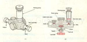
Figure 26: Fuel feed pump
The fuel feed pump (feed pump) is provided to supply fuel from the fuel tank to the injection pump. As shown in Fig. 26, the inlet check valve, piston, piston spring, tappet, push rod, and outlet check valve. , A priming pump, etc., which is a device that pumps fuel by reciprocating the piston by driving the cam shaft of the injection pump.
The priming pump is a device for manually sending fuel when bleeding air.
Operation of feed pump
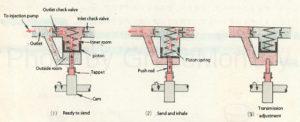
Figure 27: Fuel feed pump operation
As shown in Fig. 27 (1), when the piston is pushed up by the cam of the injection pump, the inlet check valve closes and the fuel in the inner chamber pushes open the outlet check valve to fill the outer chamber. At the same time, a portion of the fuel is sent from the outlet to the injection pump.
As the cam rotates, the piston descends due to the spring force of the return spring, and when the state shown in FIG. 27 (2) is reached, the fuel in the outer chamber is pushed out from the inlet to the injection pump.
By pushing out the fuel in the outer chamber, the pressure applied to the piston decreases, and at the same time, the pressure in the inner chamber decreases.
When the pressure in the inner chamber decreases, the outlet check valve is closed, and the pressure on the suction side becomes higher than the pressure in the inner chamber, so the inlet check valve opens and new fuel is sucked into the inner chamber from the suction side.
By repeating the pumping operations shown in FIGS. 27 (1) and 27 (2), the fuel is sent to the injection pump via the filter.
In addition, when the pressure of the fuel in the outer chamber exceeds the specified pressure (oil supply pressure), the piston remains pushed up by the pressure of the fuel in the outer chamber as shown in Fig. 27 (3) and separates from the push rod. Fuel supply is suspended.
In this way, the feed pump is a mechanism that prevents the oil supply pressure from rising above the specified value.
In addition, some feed pumps are provided with two inlet and two outlet check valves to alternately suck and deliver fuel in the reciprocating stroke of the piston.