Overhaul cylinder head
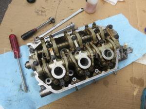
The cylinder head lowered from the engine, the engine oil management state and the state of the combustion chamber. Check the details such as distortion of the cylinder head body. Oil management often did not accumulate sludge, etc., and combustion chambers and valves etc. were never so dirty with carbon such as deposit. The distortion of the cylinder head was also measured and seems to be within the reference value. The order of overhaul is as follows.
- Remove the rocker shaft
- Remove the valve
- Measurement of cylinder head distortion
- Valve shaking
- Replacement of valve stem seal
- Install as originally
- Valve clearance adjustment
- Cylinder head mounted
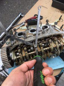
Remove the rocker shaft
Loosen the fixing bolt of the rocker arm · shaft and remove it. The rocker shaft is a spring between the orientation of the arm and the shaft. Be careful not to let the washers fall apart. When detaching, I think that it is better to remove it as a whole while shaking and bolts are not pulled out and installed. Since there is an order when assembling, refer to the exploded view. If there is no exploded view, I think that it is good to take it in the picture. By the way, the tightening torque of the bolt is 22 Nm.
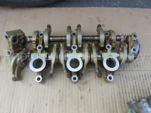
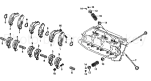
It is an exploded view of the rocker arm and the valve spring
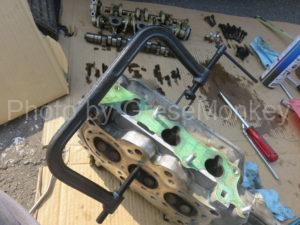
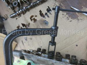
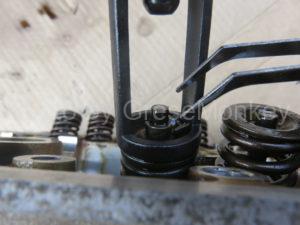
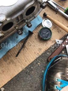
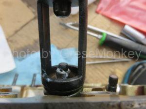
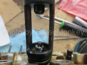
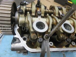
Remove the valve
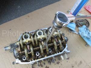
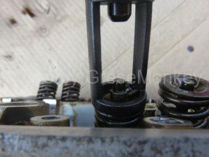
Shrink the valve spring, remove the cotter, and remove the valve. Since the cotters are very small, it is better to put them in order so that they do not get lost. With the valve spring compressor, carefully make it straight against the valve and the spring, slowly shrink the spring. Shrink it to a certain extent and see the cotter, remove it with a magnetic stick or tweezers. Once you can do it slowly loosen the spring again and remove it.
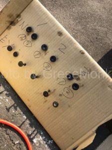
Removed valve and valve spring. Cotters are categorized as 1 to 3 of each cylinder, inlet side and exhaust side and organized. Especially valves should not be mistaken in order. This time I prepared cardboards, marked them with magic, stuck them in each case.
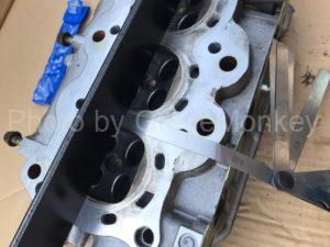
Distortion measurement of cylinder head
Measure the distortion of the cylinder head using a straight edge and a thickness gauge. If the cylinder head is distorted, even if the gasket is replaced it will not be able to obtain the proper “compression” and the engine will not work properly. Please think that the measurement point is generally the whole of the cylinder head in vertical / horizontal / diagonal / lateral center / around the combustion chamber (vertical / horizontal / diagonal diagonal with respect to the combustion chamber) of the cylinder head face. When placing the cylinder head horizontally and placing the straight edge perpendicularly to the head surface, insert the thickness gauge from the one with the thickness in that gap. At this time, put the thickness gauge sequentially from the thickness of the gauge entering the skusca, we will slowly find the point where there is a gauge thickness where the resistance goes to some extent. The thickness of the gauge before the gauge that does not enter from that point will be the “distortion value” of the measurement point of that cylinder.
In case of overheating, since it is suspected that the “missing place” confirmed with the head gasket is distorted, pay particular attention to the parts around the combustion chamber. Perfectly accurate measurement is incompatible with this method, so when it is absolutely necessary to outsource to a vendor and measure it, we recommend that you polish the face of the head cleanly.
In this example, since it was possible to measure within 0.05 mm of the distortion reference value of the cylinder head, do not put it out for polishing, but clean the head face clean with an oil stone.
Valve rubbing
We rub the valves using a special compound and rubbing stick for rubbing. In this operation, when the valved surface of the valve seat and the combustion chamber is damaged, the contact surface is rubbed with the valve itself to polish it and clean the contact surface to maintain the confidentiality of the combustion chamber. It is a work of considerable guts to be tried because it rubs on the steady road with my own hand using the octopus stick. So, there are also methods for doing with electric drills etc., but for beginners the method is not recommended much. I wondered whether or not to introduce the method this time, but I will dare to omit it. Sorry. Let’s remember what you do by hand to the steady state.
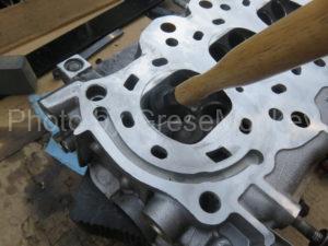
After putting an appropriate amount of compound around the valve seat, put the valve on the sucker of the octopus rod in the new world, bring your hands to the part of the bar, turn the octopus rod to visit the shrine. Even if the suction cup becomes easy to take off at this time, please reinstall it and try hard. Although it may be irritated, since the total number of valves in a 660cc three cylinder engine is 12, it should be better than an ordinary engine. Once you start you can not quit on the way, let’s polish all 12 valves until they are beautiful. This may no longer be an exercise. That is too much trouble. I’m about to cry. However, after accomplishing this work, enlightenment will be opened and the bright light of “a sense of accomplishment” will shine above your head.
When the contact surface of the valve seat gets brilliantly brilliant to a certain extent, paint “Gwangmyeong” and check the contact surface. Strictly speaking, to check the confidentiality, we set all the valves in the combustion chamber to check whether there is any leakage when filling with kerosene, but this time the state of the combustion chamber is relatively clean Because I did not do it. It is thought that it is better if you confirmed the confidentiality of the combustion chamber after grinding, etc., such as when the deposit is accumulated and the combustion chamber has been severe.
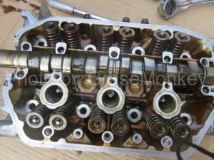
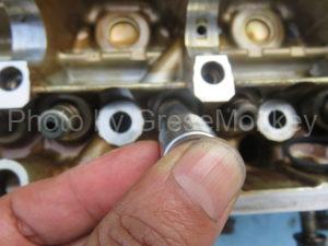
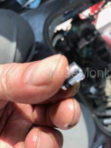
Replacement of valve stem seal
In the guide part through which the valve of the cylinder head passes, there is an oil seal called a valve stem seal to prevent the oil from dropping from the inside of the cylinder head to the combustion chamber, but this time it was replaced with a new one as well.
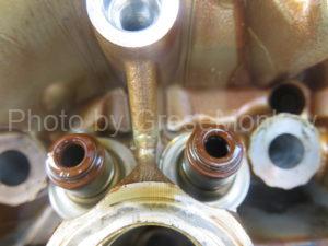
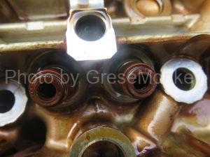
The replacement method is simple, remove the old stem seal with pliers, etc. When installing it, just bite a 10 mm 12 sided socket and push it with your hands. I think that it would be better to quit because hammers and others think that it will cause damage to the seal. This is the same as the number of valves and there are 12 places. On the inlet side and the exhaust side, the color of the small spring attached to the valve stem seal is different and the inlet side is silver. The exhaust side is black. I will not mistake it.
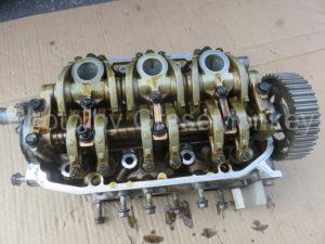
Install as originally
If you can do the work so far, I will install it as it is. The procedure is as follows.
- Assemble the valve as originally attached
- Attach valve spring and cotter with valve spring compressor
- Assemble rocker arm · shaft
- Apply engine oil to the sliding parts of the camshaft and the rocker arm · shaft, etc.
- Attach rocker arm · shaft (tightening torque 22 Nm)
- Attach camshaft and sprocket (tightening torque 56 Nm)
When installing a cotter, it is mounted with tweezers etc. with the spring spring compressor shrunk, but if you try to attach it to the notch part of the valve, the cotter is very small, because the position slips off slipping off, Using grease etc. can be set accurately.
After assembling everything, be sure to check whether there is no mistake.
Also assemble the rocker arm / shaft is a little troublesome, so post an exploded diagram.
Valve clearance adjustment
Once the cylinder head is assembled, adjust the valve clearance. I can do it even after assembling the engine, but this time I will try to adjust with cylinder head only. Basically, it is to adjust the valve clearance between the inlet side and the exhaust side of each rocker arm when the 1st to 3rd cylinders are set to the compression top dead center respectively.
Place the cylinder head sideways and make sure the position on the valve can be confirmed and set the first cylinder to the compression top dead center in the same way as adjusting the matching mark of the timing belt at the position of the camshaft · sprocket. In that state, insert a thickness gauge into the gap between the valve spring and the rocker arm, loosen the 10 mm lock nut, and turn the adjustment screw at the center with a flat head screwdriver to adjust it.
Loosen the adjustment screw until the adjustment screw is tightened with a flathead screwdriver until the thickness gauge does not come off and the gauge comes out in a state where there is little resistance from that state. When that is done, tighten the 10 mm lock nut and fix it. Do this at all valve locations.
Valve clearance adjustment values are as follows.
- Valve clearance
- Inlet side: 0.15 to 0.19 mm
- Exhaust side: 0.23 to 0.27 mm
After adjusting the first cylinder side, as you rotate the position of the camshaft · sprocket to the left side, the third cylinder becomes the compression top dead center this time, so adjust the valve clearance in the same way. When further turning to the left, No. 2 cylinder becomes compression top dead center. From this we can see that the combustion order of this engine is 1-3-2. Also, the judgment as to whether or not it is the compression top dead center can be made by checking that four valve clearances can be confirmed in one cylinder and it is in a measurable state, and the long diameter of the rocker arm and the cam shaft at that position It is situated at the opposite angle where it is not acting.
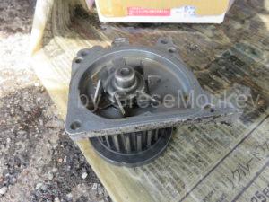
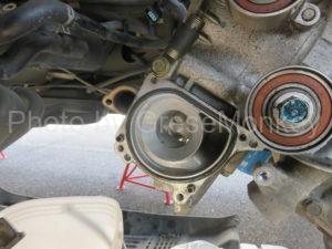
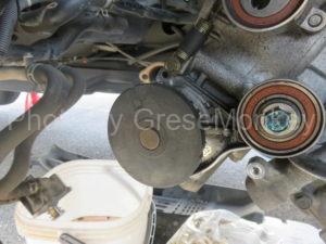
Install orifice O ring
Before installing the cylinder head, there is a part called a small engine oil orifice on the cylinder block side, but do not forget to install this. This part, which the manufacturer designates to replace at the time of engine OH, is a passage for engine oil, but if it is clogged, it seems to cause overheating. So do not forget to order it when ordering parts.
Installation is not difficult, just remove it with pliers and push it with your fingers. It looks trivial, but let’s do it without getting tired.
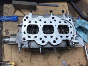
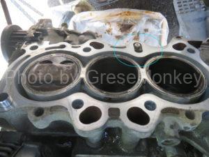
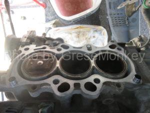
Head gasket and overheat
I will examine the cylinder head gasket that I removed. This engine has a water jacket so as to surround the cylinder liner on the block side, but there was a trace of missing towards the water jacket in both the cylinder / block per side and the cylinder / head abutment side. It is thought that the gas in the combustion chamber leaks into the water jacket from there and circulates in the water line, it becomes air chewing, the cooling water temperature rises and overheated, but because the head gasket is weak in the first place, Or because the car’s waterline is structured to allow air to be chewed for some reason, because there is a distance between the radiator and the engine body, the waterline is too long, so the radiator cap is not functioning, etc. It seems that opinions are being stated on the net.
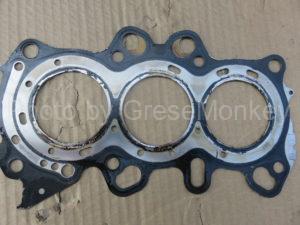
Cylinder block contact surface
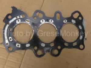
Cylinder head contact surface
By the way, the new head does not change as much as the shape, but it seemed to be redesigned with increasing strength, or slightly thicker. As for me, as with many cars, cars with a long distance between the radiator and the engine body in the rear engine are very difficult to bleed the cooling water, and even if they do proper maintenance, the air is slightly I am afraid that I am running continuously while I remain. If the position of the radiator can not be changed due to the structure of the car, I will think about adding another radiator cap and subtank to the position near the waterline engine, but I do not take reality any way Right. I think it would be nice if we could take a bit more opinions from the structure of this car and make a better way to improve overheating, but it seems difficult.
Installation of cylinder head
When the OH of the cylinder head is completed, put a new gasket on the engine block and load the cylinder head from above. At this time, it is easier to install the water pump on the timing belt side first. Then, on the cylinder block side, rotate the crankshaft to make the first cylinder the compression TDC. This is the same as when replacing the timing belt, when aligning the alignment mark of the crankshaft sprocket, the position of the piston in the cylinder is located at the compression TDC (the highest position) It is bad.
Also in the cylinder head, please rotate the camshaft so that the first cylinder becomes the compression top dead center (align the matching mark of the camshaft sprocket).
Although it is basic, this engine rotates counterclockwise, the timing of one revolution of the camshaft per crankshaft two rotations. So, for example, even if the matching mark on the crankshaft is aligned, if the first cylinder does not become the compression top dead center, it should be done another rotation. Then, in order to confirm the condition that the first cylinder is the compression top dead center in the cylinder head, with the matching mark of the camshaft sprocket aligned, the state of the valve of the first cylinder combustion chamber is changed to the state of the inlet and the exhaust It is said that both are closed and that the camshaft is not acting.

After confirming the above, set the head gasket to the correct position and carefully place the head. Once mounted, temporarily tighten the cylinder head bolts equally. At that time, make sure that the cylinder block side and the head gasket, cylinder head are surely docked, and then complete tightening. This is also basic in the basic, but in the reverse order when loosening from the center of the head, firstly tighten equally with a wrench to some extent, then apply torque properly with a torque wrench. This work also needs to be done with considerable nerve.
- Cylinder head bolt tightening torque
- 64Nm(65kgf/m)
- Tightening order of cylinder head bolts (loosening order)
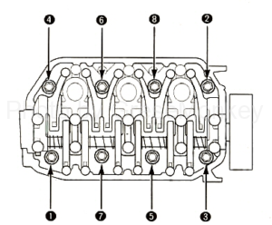
Cylinder head bolt loosening order is cited from maintenance manual. When tightening, it should be in reverse order of this order, drawing a diagonal line from inside to outside of the cylinder head.
When installing the cylinder head, install the exhaust system, etc., in order of the intake system and electrical system. After that I install the timing belt, but I attach the tappet cover last.