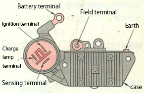
Battery alternator and dynamo
The batteries (12v, 24v) used in automobiles are DC power supplies, so when you charge this battery, you will still need a DC power supply. Normally, a generator generates an AC power supply by an internal rotating mechanism, and further converts the AC power supply into a DC power supply by a rectifier before charging a battery. Until the 1950s, there was no suitable rectifier suitable for automobiles at that time, so a direct current generator was used as it was. And this was called “dynamo”.
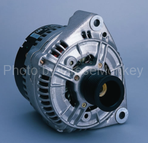
By the end of the 1950s, inexpensive, compact and high-performance rectifiers were developed, and instead of DC generators, AC generators equipped with this rectifier were used to convert AC to DC. It was This is called an “alternator”.
By adopting an alternator, the power generation capacity (charging capacity) at a low speed can be significantly improved, and the maintenance of commutator and brush, which has been a long-standing problem, has been released. ..
The conversion to this alternator also took place at a very fast speed, and even Japanese cars were almost finished in the latter half of the 1960s.
Table of contents
- Difference between DC generator (dynamo) and AC generator (alternator)
- Characteristics of alternator
- Alternator structure
- Three-phase AC rectification (rectified to DC current)
- Function of voltage regulator
- Current charger
Difference between DC generator (dynamo) and AC generator (alternator)
In both cases, the principle of power generation is still based on the use of the electromagnetic induction effect that an electromotive force is generated in the conductor wire when the conductor wire moves in the magnetic field (conversely, the magnetic field may move).
That is, when the magnetic flux passing through the conductor is changed, an electromotive force is generated in the conductor so as to cause a current to flow in the direction in which the change in the magnetic flux is prevented. The relationship between the direction in which the current flows and the direction in which the magnetic field moves the conductor can be explained by “Fleming’s right-hand rule.”
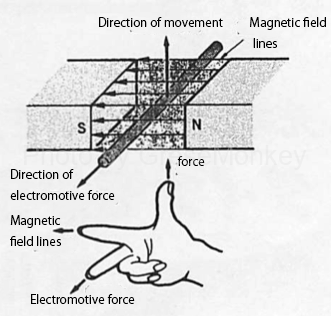
Figure 1: Fleming’s right-hand rule
In case of DC generator (dynamo)
In FIG. 2 below, when the coil (ring of conductive wire) is rotated to the right, electromotive force is generated in the direction of the arrow in the figure, as indicated by Fleming’s right-hand rule. If the coil continues to rotate and passes the point where the coil surface is perpendicular to the direction of the magnetic force line, the direction of movement of the conductor with respect to the magnetic force line is the opposite direction (from downward to upward), so the direction of current flow is also opposite. Should be.
However, since there is a commutator, the coil surface becomes vertical (the commutator piece in the figure is the cut at the position where the coil surface is vertical, so it is the cut portion of the commutator. The connection with the brush that is in contact with the commutator piece is lost.) Once the current is cut off, the connection with the brush that is in contact with the commutator piece is switched. The direction of the current flowing from the brush to the load remains unchanged. That is, it becomes direct current. This is the principle of DC power generation.
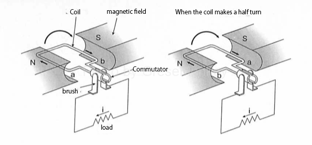
Figure 2:Operating principle of DC power generation
In the case of a commutator that does not have a commutator piece and continues to be in contact with the brush as it is, the direction of the current becomes the opposite direction when the coil surface becomes the vertical position, and the current becomes the AC instead of the DC. To solve this problem, the commutator is cut at a half-turn (180°) position.
The structure of this commutator and brush was incomplete and caused various troubles depending on the maintenance. In low-speed rotation that does not reach the charging voltage, a cutout relay is required to prevent backflow from the battery, and the charging capacity at low-speed rotation is low, and the armature (armature) coil is not good at high-speed rotation. For this reason, when a compact and highly reliable silicon diode rectifier was developed, it was replaced by an alternator.
For AC generator
The principle of power generation is the same as that of a DC generator, but the way of extracting the generated electromotive force is different. Figure 3 below shows the principle of an alternator, but with both ends of the coil connected to a slip ring instead of a commutator. In that case, since the connection state between the slip ring and the brush does not change, the coil rotates and the direction of the electromotive force generated in the coil also changes. This is the principle of AC power generation.

Figure 3: Working principle of an alternator (rotating armature)
However, in an actual alternator (alternating current generator), the coil that generates electric power is wound around the stator side and does not rotate, but the magnet side rotates. Therefore, this is sometimes called a field rotation type or a field rotation type.
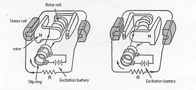
Figure 4: Working principle of AC generator (field rotation type)
The rotating magnet (rotor) is excited by an exciting battery and a rotor coil. (Excitation: Generates magnetic flux) Therefore, the current flowing through the slip ring is not the output current but a small current for excitation, so that the life of the slip ring and brush can be further extended.
This is one of the characteristics of the alternator.
A brushless vehicle may be used in a large vehicle that requires a longer life.
It should be noted that the battery for excitation uses the battery actually mounted on the vehicle, and when the alternator starts power generation, a part of the output is used for excitation.
Even with the same AC generator, many bikes use permanent magnets for the rotating magnets, simplifying the structure. Further, the rotary magnet is an outer rotation type that rotates around the power generation coil and is a part of the flywheel mass.
Characteristics of alternator
The features of the alternator are summarized below.
- Due to its structure, it can be rotated at high speed, so it can be made compact and lightweight. (Although the armature coil of a DC generator cannot withstand centrifugal force and rotate at high speed, the rotor coil of the alternator is wound directly around the center of the rotor core (ball), has a small diameter, and can rotate at high speed. Therefore, the engine speed at idle can be set high, which leads to an improvement in power generation output at low engine speed.
- Since the rotor coil (field coil) is a separately excited type that is excited by a battery, it is possible to generate power even when idling. (The current flowing through the field coil of the DC generator depends on the output, so the output at low speed rotation is extremely small.)
- Since the slip ring is used instead of the commutator, and the current flowing through the slip ring is not the output current but the exciting current of the rotor coil, which is a small current, the brush life is long and maintenance is easy. It is also possible to make it brushless.
Power generation output characteristics
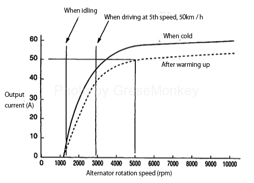
Figure 5: Power generation output characteristics
From Fig. 5, taking an example of the power generation output characteristics, although the output at low speed rotation was improved, only about 10 to 20% of the rated output is output at idle. Therefore, when the engine speed is low, such as during idling, the amount of power that can be generated is less than the required amount of power, so the battery will make up for the shortage. And as the number of revolutions increases, there is more output, so the extra power is used to charge the battery.
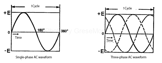
Figure 6: Single-phase AC and three-phase AC
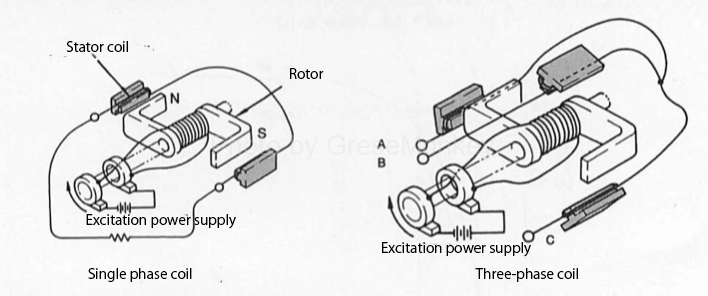
Figure 7: Single-phase and three-phase coils
In FIG. 4 above, the alternating current generated is a single-phase alternating current (see FIG. 6), but the actual alternator is a three-phase alternating current. Three-phase AC can be obtained by increasing the number of coils on the stator side to one (see Fig. 7)
Alternator structure

Figure 8: IC alternator
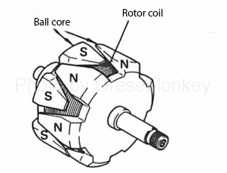
Figure 9: Rotor
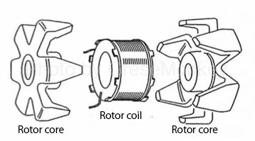
Figure 10: Rotor structure
Rotor and stator
The rotor is as shown in Fig. 9, but the structure is as shown in Fig. 10. The rotor coil (field coil) is sandwiched between two rotor cores. Therefore, when an exciting current flows from the split ring to the rotor coil, the two rotor cores are excited to the N pole and the S pole, and the N pole and the S pole are alternately arranged on the surface facing the stator core. The rotors in Fig. 4 and Fig. 7 can be thought of as a set of north and south poles taken from the actual rotor.
In the case of the brushless type, the rotor coil rotates in a non-contact state around the rotor coil fixed to the alternator housing. A motor normally has a structure in which a coil wound with a copper wire rotates inside a permanent magnet, but if this structure is reversed to rotate the permanent magnet side, it is not necessary to make a brush. (See Figure 11)
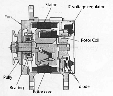
Figure 11: Brushless rotor
In this way, the rotor can be multi-polarized with a simple structure, and can have the strength to withstand high-speed rotation and high efficiency.

Figure 12: Stator
The stator on the side that generates electromotive force is shown in Fig. 12. It is easy to understand by considering that three coils are wound according to the number of poles of the rotor core in order to obtain three-phase alternating current. In other words, if we consider that the alternators that are as small as the number of poles of the rotor core are connected in series, the image shown in Fig. 13 is obtained.
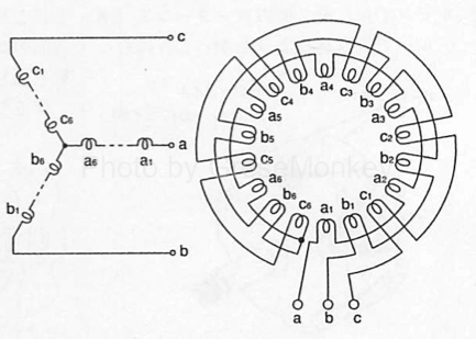
Figure 13: Connecting the stator coils
Since the alternator generates electricity, a current flows through the coil, which is a kind of resistor, and thus heat is naturally generated. Therefore, a cooling fan is installed to prevent coil insulation and damage to the diode.
The alternator is usually driven by a fan belt from the crankshaft, but the rotation speed is about twice that of the crankshaft.
Three-phase AC rectification (rectified to DC current)
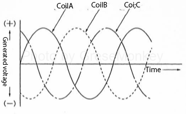
Figure 14: Alternator generated voltage
When the rotor rotates, out-of-phase electromotive force is generated in the three coils of the stator. (See Fig. 14) This is called three-phase alternating current.
However, in this state of electromotive force, it cannot be used for electric parts of automobiles such as battery charging, so it must be rectified to direct current. The connection state with the diode used as the rectifier is as shown in FIG. 15. By rectifying the three-phase AC shown in FIG. 14, a DC as shown in FIG. 16 can be obtained.
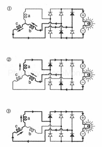
Figure 15: Operation of the three-phase full-wave rectifier circuit 1
Figure 15: Operation of the three-phase full-wave rectifier circuit 2
The state of point A in Fig. 16 is the state of ③ in Fig. 15, but since the negative (-) voltage generated in coil c is larger than the negative (-) voltage of coil b at this time, the current is coil a. Flows through the load to coil c. The rectified voltage is equal to the difference between the voltages generated in the coils a and c, that is, the voltage of the coil a plus the voltage of the coil c indicated by the white arrow (<==>). (Actually, since the voltage difference between a and c is, the formula is: “voltage difference of coil a at point A-(voltage difference of coil c at point A)) = = voltage difference of coil a at point A + Voltage difference of coil c at point A”

Figure 16: Voltage after rectification
In this rectifier circuit, whichever direction the voltage is generated in the coil can be used as a direct current flowing in a fixed direction, this rectification method is called a full-wave rectifier circuit. On the other hand, a rectification method that can take out only one side voltage (one direction) of alternating current is called half-wave rectification.In this case, rectification reduces the power after rectification by half and occurs. Power cannot be used effectively.
In full-wave rectification, the magnitude and direction of the current flowing through the three coils change in sequence, but the current always flows in a fixed direction on the load side.
Since the diode allows the current to flow only in one direction, it is possible to prevent the reverse flow of electricity from the battery when the generated voltage of the alternator is low. In other words, the cutout relay for backflow prevention, which was necessary in the case of a dynamo (DC generator), is no longer necessary.
Function of voltage regulator
Since the induced electromotive force due to electromagnetic induction is proportional to the speed at which the magnetic flux passing through the coil changes, the voltage generated by the alternator is proportional to the rotational speed and the magnitude of the speed, that is, the magnetic force of the rotor (excitation current of the rotor coil). Will be done.
Therefore, since the generated voltage increases as the rotation speed increases, the voltage is not stable and is not so good when driven by a prime mover whose rotation speed fluctuates greatly like an automobile engine. Therefore, the role of the voltage regulator is to always keep the generated voltage constant even if the rotation speed changes.
The operating principle of the voltage regulator is to pay attention to the fact that the voltage generated by the alternator is proportional to the exciting current, and to control the exciting current flowing through the rotor coil so that the generated voltage is adjusted to be constant.
The voltage regulator has a contact type and an IC type, but at present, it is small and highly reliable, and the IC type that can be built into the alternator is used. This is because the IC type is a contact type, and there are no contacts that could easily cause a failure, and there is no contact.
IC type voltage regulator
Contact type voltage regulator
In the case of the contact type, as the number of rotations of the alternator increases and the generated voltage increases, the electromagnetic force of the regulator coil also increases, so the attraction force is generated and the point opens. After that, since the resistance is connected in series to the field coil, the current of the field coil is reduced and the generated voltage is reduced. (See Figure 17)
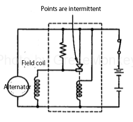
Figure 17: Contact voltage regulator
IC type voltage regulator
In the case of the IC type, the Zener diode becomes conductive when the generated voltage becomes high. At this time, the transistor Tr1 is turned on and the transistor Tr2 is turned off, so that the current of the field coil is reduced and the generated voltage is reduced. (See Figure 18)
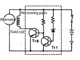
Figure 18: IC type voltage regulator
When the generated voltage drops, the Zener diode becomes non-conductive, the transistor Tr1 is turned off, and the transistor Tr2 is turned on, so that the current in the field coil increases and the generated voltage increases.
The circuit diagram of the actual charging system is shown in Fig. 19.
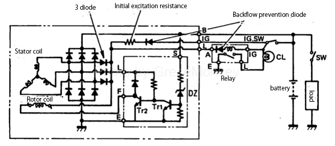
Fig. 19: Circuit diagram of charging system
Current charger
It seems that current chargers such as alternators are almost complete, but with the recent development of sensors and electronic controls, fine-tuned control aimed at further improving charging efficiency and improving fuel efficiency of automobiles has been carried out. It is being appreciated.
For example, charging control is performed according to the running state. When acceleration or climbing that requires engine output, the generated voltage is lowered so that it does not charge much, and when the accelerator (throttle valve) is closed and decelerated, the generated voltage is raised to ensure proper charging. The idea is to recover the kinetic energy of the car when decelerating and use it to charge the battery. If anything, there seems to be something close to hybrid car technology.