Inspection and maintenance of old car gasoline engine
In order to maintain the engine in the best condition and fully demonstrate its performance, it is necessary to carry out regular inspections and maintenance. Basically, what is required of a gasoline engine is three elements: “strong compression pressure”, “appropriate ignition timing and strong sparks”, and “appropriate air-fuel mixture”.
Therefore, the inspection and maintenance of the engine here will explain the inspection and maintenance method including the regular maintenance and management, which is the basis of the inspection and maintenance of the engine, focusing on these three elements.
When inspecting and servicing an engine, the structure and functions are well understood, and the inspection and maintenance method and maintenance standard values are set for each engine, so the correct work procedure should be done using appropriate tools, equipment, instruments, etc. It is necessary to carry out inspection and maintenance work at.
table of contents
- Checking engine oil
- Inspection of cooling water (LLC)
- Inspection of drive belts for auxiliary equipment
- Inspection of air cleaner
- Inspection of fuel filter
- Battery inspection
- Inspection of spark plugs
- Inspection of high tension cord
- Inspection of contact points
- Check valve clearance
- Checking the compression pressure
- Inspection of fuel pump
- Inspection of ignition sparks
- Ignition timing check
- Checking idle speed
- Checking the exhaust gas condition (CO / HC concentration)
Checking engine oil
Check engine oil for quantity and dirt and for leaks from the engine.
- Regarding the amount of oil, the car is leveled, the engine is stopped, and after a certain period of time, the oil returns to the oil pan from each part, and the oil level is checked with an oil level gauge in a stable state, and it is insufficient. If so, replenish.
- Please note that depending on the model of the engine, the engine warning lamp may light up if the amount of oil is not the proper amount based on the measurement of the oil level gauge.
- For oil leaks, check for leaks from the oil seals, oil pan mounting surface, hoses, and pipes, and if there are leaks, retighten if there are loose bolts or the like. , Replace any defective oil seals or hoses.
- Check the oil for dirt with an oil level gauge, and if it is abnormally dirty, replace it. If there is a provision for regular replacement of oil and oil filter, replace it according to the distance or period. In the case of a gasoline engine, the standard is that the mileage is approximately 3,000km to 5,000km or the oil filter is replaced every six months, and the oil filter is every 10,000km, but it depends on the condition of the engine and the maintenance status. If necessary, it is necessary to replace it and check not only the oil for dirt but also the viscosity of the oil and the presence of foreign matter at the time of replacement, and the temperature of the oil at the time of replacement. Be sure to use the correct viscosity and type of oil for the vehicle to be replaced with a new one, and never reuse engine oil or add non-engine oil.
Inspection of cooling water (LLC)
Check the amount, dirt, leaks, etc. of cooling water (LLC).
- The amount of cooling water is checked in the sub tank, and if it is insufficient, it is replenished to the specified level.
- When replenishing the cooling water, mix the specified amount of LLC (antifreeze). If the cooling water is replaced or a large amount of cooling water is replenished, air will be mixed into the cooling system, so the engine should be idle for several minutes to bleed the air. In this case, the air is released and the level of the cooling water drops, so the cooling water is replenished to the specified level again.
- Basically, it is desirable that the air bleeding work when exchanging the cooling water is performed according to the cooling water exchange manual of the vehicle. Depending on the vehicle, it is difficult to bleed the air when exchanging the cooling water, and it takes time or troublesome work.
- Vehicles with a complicated cooling system or vehicles with a distance between the engine body and the radiator (rear engine, midship engine, etc.) have a long cooling system distance (layout of hoses, piping, etc.) and tend to be difficult for air to escape. Since there is, do the air bleeding work based on the manual etc.
- Except for vehicles that use Super LLC, which is recommended to be replaced every 100,000 km, older vehicles require the use of a stock solution of LLC diluted with tap water. The dilution ratio is basically “water: LLC = 6: 4”, but for vehicles with designation, follow that.
Inspection of drive belts for auxiliary equipment
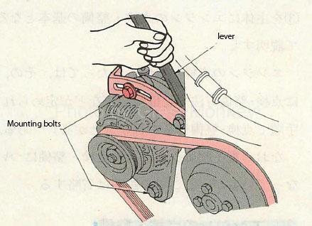
Figure 1: Alternator drive belt adjustment
Check for tension and damage to the drive belts of auxiliary equipment such as alternators, power steering pumps and compressors.
- For belt tension, measure the amount of deflection when the middle of the belt between the specified pulleys is pushed with the specified force, and adjust so that this value becomes the specified value. (Basically, it bends 1 cm with a force of 10 kg)
- The alternator drive belt is adjusted by loosening the mounting bolts and applying an appropriate lever to the alternator body as shown in Fig. 1 and applying the principle of leverage. In addition, there are those that have an adjust bolt in the alternator body and those that adjust the belt by providing a separate adjustment mechanism between the crank pulley and the alternator pulley. There is also an automatic adjustment type that keeps the tension of the belt constant by using the torsional force of the torsion spring.
- If the amount of deflection of the belt is large (loose tension), the belt may slip, and if the amount of deflection is small (too much tension), not only the belt itself may wear faster, but also the bearings of accessories such as alternators may be damaged. So be careful.
- If the belt is severely damaged (cracked, deteriorated, etc.), replace it.
Inspection of air cleaner
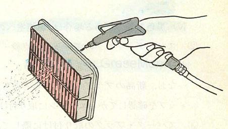
Figure 2: Cleaning the air cleaner
The air cleaner is inspected for damage and dirt on the element.
- Clean and replace the element every specified mileage. If the element is clogged, clean it by blowing air from the inside as shown in Fig. 2.
- The viscous type (wet) element is not cleaned with air and is replaced every specified mileage. In addition, when the usage conditions are severe such as continuous driving on a dusty road, the replacement mileage is shortened in the case of the viscous type.
Inspection of fuel filter
Cartridge type (non-disassembled type) is replaced every specified mileage. When replacing the filter of the electronically controlled fuel injection device, be sure to lower the fuel pressure in the fuel pipeline to prevent fuel from being ejected.
Battery inspection

Figure 3: Battery specific gravity measurement
Check the battery for liquid volume, liquid specific density and mounting condition.
- Check that the electrolyte in each cell of the battery is within the specified level line, and if it is insufficient, replenish with purified water or distilled water.
- As shown in Fig. 3, measure the electric meter liquid specific density of the battery using a hydrometer. At this time, if the specific gravity is 1.220 (liquid temperature 20 ° C) or less, supplementary charging is performed.
- When supplementary charging on the vehicle, remove the battery terminal to prevent damage to the electronic control device parts.
- Clean the battery mounting area, terminals, and upper part of the battery, and check for corrosion and damage. Since the terminal part of the battery is tapered, insert the terminal firmly as far as it will go and attach it, and tighten the nuts with an appropriate torque.
- After attaching the terminals, apply grease or the like to prevent corrosion.
Inspection of spark plugs
The spark plugs should be inspected for burns, burnouts, spark plug gaps, etc. Iridium plugs, which are recommended to be replaced every 100,000 km, are maintenance-free.
Visual inspection
Visually inspect the burnt condition of the plug and judge whether it is good or bad.
- If it is light brown, the engine is in good condition and the heat value (heat range) of the plug is also appropriate.
- If it is white, the cause is that the engine is overheated, the heat value of the plug is too low, or the air-fuel mixture is too thin. => Overburned plug
- When it is black and dry, it is generally the opposite of the case where it is white, and it is caused by the mixture being too rich, the heat value of the plug being too high, and the like. => The plug is not burnt.
- If it is black and moist, the cause is oil intrusion into the combustion chamber or fuel fog due to misfire of the plug (the plug gets wet with fuel).
Plug gap adjustment
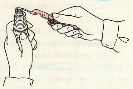
Figure 4: Spark gap inspection
- Check and adjust the spark plug gap using a spark plug gauge as shown in Fig. 4.
- When using a new plug, check the gap before attaching it to the engine.
- To clean the gap, use a # 200 to # 300 paper file to lightly polish the gap.
Plug installation
In the case of an aluminum alloy cylinder head, in order to prevent damage due to overtightening, when tightening, do not use a tool that rotates at high speed such as an air ratchet, but manually rotate and attach it while checking the engagement of the screw holes of the plug and head. Use a suitable tool to tighten to the specified torque.
Inspection of high tension cord

Figure 5: Checking the resistance value with a circuit tester
Check the assembled condition and resistance value of the high tension cord (plug cord).
For inspection of the assembled condition, make sure that the cord terminal is securely inserted into the distributor’s cap, ignition coil, or spark plug.
To measure the resistance value, use a circuit tester to measure the resistance value between both ends of the high tension cord, and replace it if it exceeds the specified value.
Inspection of contact points
Inspect the contact surface of the contact point for damage and point gaps.
Inspect the contact surface of the contact point and replace it if it is damaged. A small amount of the specified grease is applied to the point heel part (point edge part).
Inspection and adjustment of point gap
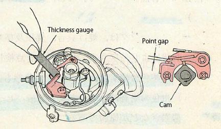
Figure 6: Checking the point gap
- Check the alignment of the points, and if the contact is poor, bend the arm of the point on the contact base side to adjust.
- The point gap should be inspected using a thickness gauge as shown in Fig. 6 with the heel of the breaker arm riding on the rearmost part of the cam (the maximum position of the point gap). If the gap is not the specified value, check it. , Loosen and adjust the contact base mounting screws.
Check valve clearance
The valve clearance should be inspected and adjusted when the engine is warmed up when the valve is warm, and when the engine is cold when the valve clearance is cold.
Inspection and adjustment of valve clearance
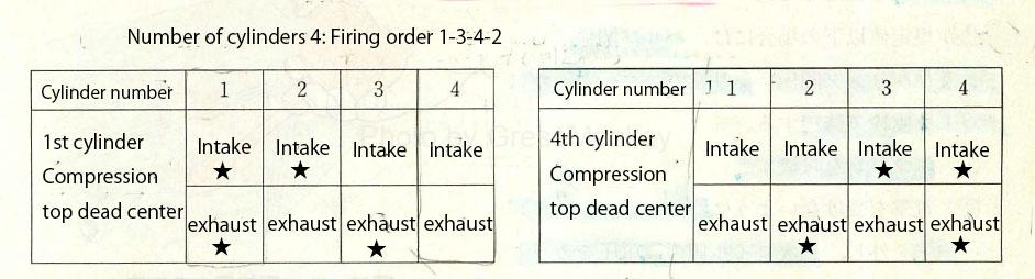
Table 1: Valve clearance measurement method
To measure the valve clearance efficiently, set the 1st cylinder to the compression top dead center, inspect and adjust the valves marked with ★ in Table 1, then rotate the crankshaft once to compress the 4th cylinder. There is a way to check and adjust the remaining valves at dead center.
Valve clearance measurement
- In the adjust screw type, a thickness gauge is inserted between the valve stem end face and the adjust screw end face of the rocker arm for measurement. Some engines measure between the cam and the rocker arm.
- In the adjust shim type, measurement is performed between the camshaft and the adjust shim or tappet.

Figure 7: Valve clearance adjustment (adjustable screw type)
Valve clearance adjustment
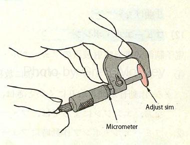
Figure 8: Adjustment shim measurement
- As shown in Fig. 7, the adjust screw type is adjusted so that the thickness gauge is slightly responsive and can be pulled out with the adjust screw of the rocker arm.
- In the adjust shim type, the adjust shim is removed from the tappet, the thickness of the adjust shim is measured at the contact surface of the cam (near the center) using a micrometer as shown in Fig. 8, and the valve clearance is new so that it becomes the specified value. Select the adjust shim, attach it to the tappet, and check again that the valve clearance is within the specified value.
- Since some adjustment shim type adjustments involve removing the camshaft, measure the valves of all cylinders in advance, and check the shim thickness to be selected by the following formula where adjustment is required. Do it afterwards.
- Thickness of selected shim = Thickness of removed shim + (measured valve clearance-specified valve clearance)
Checking the compression pressure

Figure 9: Compression pressure measurement
The compression pressure is measured from the following order using a compression gauge as shown in Fig. 9, and if the value is less than the specified value, check and correct the valve, piston and cylinder, and cylinder head gasket.
- Warm up the engine
- Remove the high tension cord so that it will not be hit by electric shock, and cut the high voltage on the secondary coil side. In the electronically controlled fuel injection device, the injection of fuel is stopped by performing work such as disconnecting the connector of the injector.
- Remove the spark plugs of all cylinders and install the engine tachometer.
- Securely attach the compression gauge to the mounting hole with the spark plug of the cylinder to be measured. (Press)
- Depress the accelerator pedal (throttle valve fully open), rotate the starter, and read the compression pressure when the pointer of the compression gauge stabilizes (maximum value).
- Perform the above work for all cylinders, one cylinder at a time.
- Precautions when measuring compression pressure
- Use a fully charged battery and the engine will run at 250 rpm or higher.
- For compression gauges that use rubber hoses, do not bend the hose.
Inspection of fuel pump
A simple inspection of the fuel pump of the electronically controlled fuel injection device is performed according to the following procedure.
- Check that the fuel pump makes a noise for a few seconds after the ignition switch is turned on. If the operating noise is hard to hear, remove the fuel tank cap and check from the inlet. Depending on the engine, the fuel pump inspection terminal may be short-circuited.
- When operating the fuel pump and pinching the fuel hose with your fingers, check that the hose is taut or pulsating.
Inspection of ignition sparks
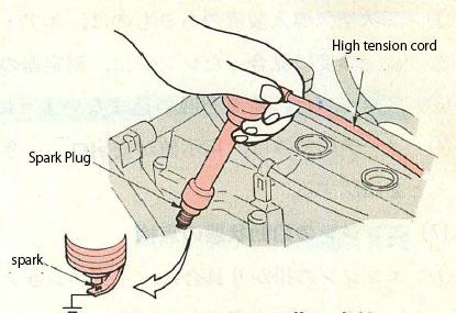
Figure 10: Inspection of ignition sparks
Make sure that strong sparks are flying on the spark plugs of all cylinders.
- Remove the spark plug and attach it to the high tension cord.
- Ground the ground electrode of the spark plug as shown in Fig. 10 and check that sparks fly when cranking.
- In the case of an electronically controlled fuel injection device, work such as always disconnecting the injector connector is performed so that fuel is not injected.
Ignition timing check
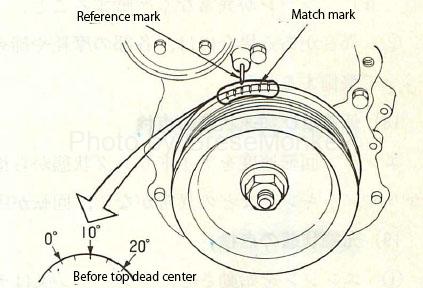
Figure 11: Ignition timing adjustment
To check the ignition timing, after warming up the engine, keep it idling and the advance function is stopped, and use a timing light to mark the alignment mark on the crank pulley as shown in Fig. 11. And illuminate the reference mark to confirm that both marks match. If they do not match, generally the distributor body is turned to adjust.
Also, confirm that the ignition timing advances smoothly when the engine speed is increased.
It should be noted that the method of fixing the brain to the advance angle differs depending on the engine.
Checking idle speed
The idle speed is checked by connecting the octopus tester to the primary terminal of the ignition coil or the engine speed detection terminal.
Warm up the engine so that no electrical load is applied, and check that the idle speed is at the specified value under no load. If it is not the specified value, adjust it with the idle adjust screw. (Carbator)
If the idle speed is controlled by ISCV or the like, confirm that the specified idle speed is maintained when an electric load is applied to the engine.
Checking the exhaust gas condition (CO / HC concentration)
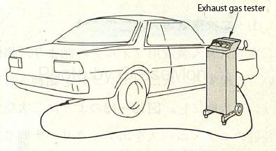
Figure 12: Measurement of CO / HC concentration
Before measuring the CO and HC concentrations, in principle, check and adjust the spark plug, distributor, ignition timing, idle speed, etc. in advance.
- For those with secondary air injection, plug the air hose to cut the secondary air.
- Set the range selector switch of the measuring instrument to the range that matches the measured concentration.
- Insert the probe 60 cm or more into the exhaust pipe as shown in Fig. 12 so as not to inhale air.
- Read the meter when the indicated value is stable, and confirm that the CO and HC concentrations are within the specified values.