1996 formula Nissan Skyline model: E-HR33 engine model: RB25DE

The blower motor of the auto air conditioner stopped rotating at the maximum air volume
Normally, the blower motor varies the air volume by changing the voltage applied to the motor. There are two types of air conditioners for cars, which are largely classified as manual air conditioners and auto air conditioners. In the case of a manual air conditioner, the air flow rate is controlled in stages using a register. In the case of auto air conditioner, the air volume is controlled in a stepless manner by using a power transistor.
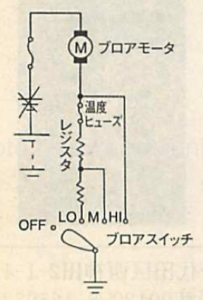
Manual air-conditioning basic circuit
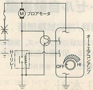
Auto air conditioner basic circuit
In either of the manual air conditioner and the auto air conditioner, since the battery voltage is directly supplied without passing through the register or the power transistor in the case of the maximum air flow rate, it is possible to determine whether the blower motor rotates as it is Good / bad judgment can be done
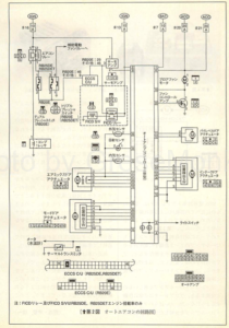
In this case, since the blower motor does not rotate even if the maximum air flow rate is set, it is necessary to inspect the power supply circuit and the motor itself. For this reason, when the 19th terminal of the auto amplifier of the circuit shown in the circuit diagram is grounded, the motor rotates vigorously, so it was judged that there is no problem with the circuit so far. Then, I searched for “Hi” relay which controls the maximum air volume of the blower motor, but since I can not find it, I contacted the manufacturer.
According to the new manual issued by the manufacturer, it is found that what is called a “MOS field effect transistor” rather than a conventional power transistor is used. (MOS = Metal Oxide Semiconductor)
MOS Field Effect Transistor
MOS field effect transistor seems not to need the “Hi” relay like so far because there are fewer electric conductors by internal resistance than conventional MOS field effect transistors. (Refer to the circuit diagram below)
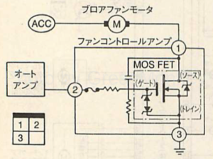
Fan control amplifier circuit diagram
When setting the voltmeter at the NO 2 and NO 3 terminals of the fan control amplifier provided in the case of the blower motor and operating the blower switch, it changed between 2 V and 10 V. From the above inspection results, it was confirmed that the fan control amplifier was defective.
Fusing of thermal fuse

Fan control amplifier appearance and internal structure in which the thermal fuse blown
When replacing the fan control amplifier with a new one, the blower motor started to operate normally. Therefore, when the fan control amplifier which broke down was disassembled, the thermal fuse was blown. This is also used for registers of the air volume control circuit of the manual air conditioner, but there are reasons for such fusion to be blown.
For example, when the room dryer becomes old, hot air does not come out, but this is because the ventilation becomes worse due to the hair and dust adhering to the suction port and the inside, the temperature rises too much and melts down.
Just like this, if the air conditioner filter and the evaporator of the car are clogged, the temperature fuse will be melted by the same principle as the above-mentioned hair drier, the air volume decreases.
Just because the thermal fuse is blown, solder it and do not repair it. This is because the thermal fuse melts at about 180 ° C., but since ordinary solder has a melting point around 220 ° C., it can be heated to cause a vehicle fire.
Using the same auto air conditioner as an example, if you do not know that the control method is subtly changing like this time, the same judgment method as before will not be accepted. Automotive technology is evolving day by day, I thought that day-to-day learning is indispensable to respond to it.