The force applied to the suspension and the car body Part 2
Inertia spindle
The main points of the previous article “Force applied to suspension and vehicle body”
Among the forces acting on the suspension arm when the car accelerates, the squat force, which is the force generated by acceleration to lower the rear part of the vehicle body, is the mounting position of the suspension arm (virtual rotation in the case of the semi-trailing arm type). By setting the center) to an appropriate position, it was possible to make it zero.
The position was on a straight line connecting the center of the front wheels with the radius of the tire and the height of the center of gravity and the center of the rear wheels.
However, in the case of the semi-trailing arm type, due to suspension operation requirements (tire alignment) and packaging restrictions (position of rear seats, floor, etc.), it seems to promote squat force rather than anti-squat. I had to set it to the position.
So this time, let’s start by thinking first about double wishbone suspensions that may solve this problem.
table of contents
- The main points of the previous article “Force applied to suspension and vehicle body”
- For double wishbone suspension
- For strut type
- Force acting during braking
For double wishbone suspension
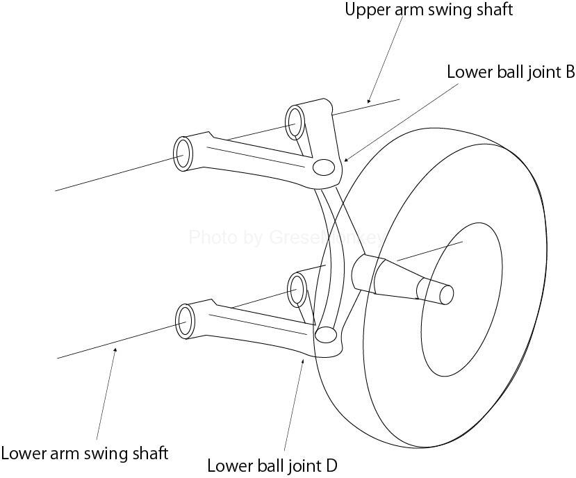
Figure 1-1: Double wishbone type rotation center
In the case of the double wishbone system, the upper ball joint B rotates around the swing axis of the upper arm, and the lower ball joint D rotates around the swing axis of the lower arm.
Looking at this in the side view (Fig. 1-2), the upper ball joint B moves up and down at right angles to the swing axis of the upper arm, and the lower ball joint D moves up and down at right angles to the swing axis of the lower arm. You will be exercising.
Therefore, the bab carrier as a whole extends the swing axes of the upper arm and the lower arm, respectively, and makes a rotational motion around the point where the extension lines intersect. (See Figure 1-2)
This is the same idea as the moment center that was sought when seeking a roll center.
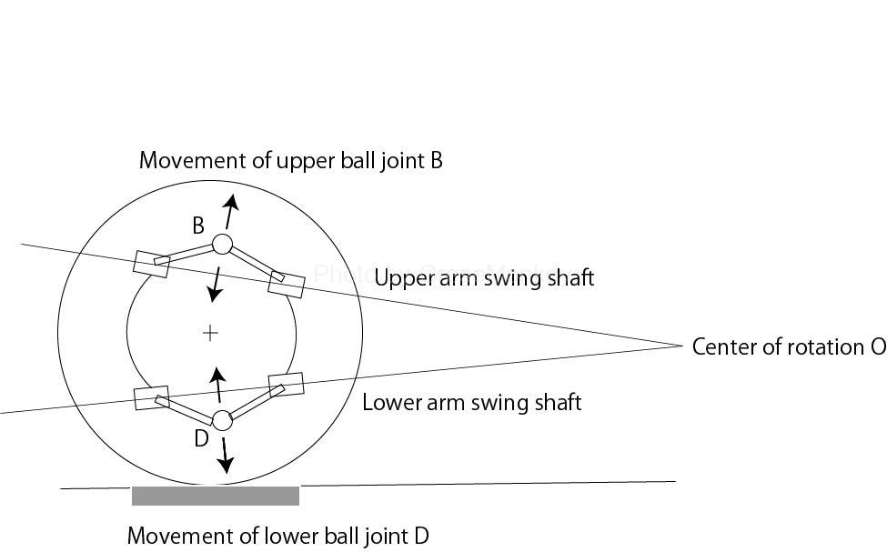
Figure 1-2: Double wishbone type rotation center
If each swing axis is parallel to the road surface and does not intersect, the position of the center of rotation O will be infinitely far away, so that the characteristics of anti-dive and anti-squat will not occur.
Strictly speaking, a straight line should be drawn parallel to each swing axis through the upper ball joint and the lower ball joint, and the point where these two straight lines intersect should be the center of rotation O.
However, since the position of the ball joint changes each time by the wheel stroke, there is not much change even if the rotation center O is the point where the extension lines of the respective swing axes intersect.
With other types of suspension, it is difficult to bring the center of rotation to the ideal position because it is obstructed by the floor and rear seats, but in the case of double wishbones, the position of the swing axis of the upper arm and lower arm and By selecting the tilt, it is possible to set the rotation center of the lower layer quite freely. This is one of the reasons why the double wishbone type and multi-link type suspensions have become the mainstream.
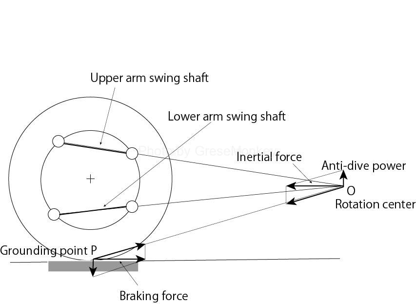
Figure 2: Double wishbone anti-dive geometry (when front-wheel drive)
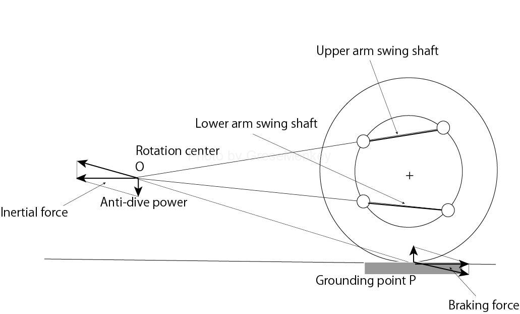
Figure 3: Double wishbone anti-lift geometry (when driving rear wheels)
The idea after finding the center of rotation O is exactly the same as in the case of the trailing arm type. FIG. 2 shows the anti-dive characteristics on the front wheel side that occur during braking, and FIG. 3 shows the anti-dive characteristics on the rear wheel side.
For strut type
In the case of the strut type, a straight line is extended at right angles to the piston rod from the attachment point B on the vehicle body side of the strut, and the center of rotation obtained by the point intersecting the straight line extending coaxially such as the lower arm is O.
The idea after finding the center of rotation O is exactly the same as for the double wishbone type and trading arm type.
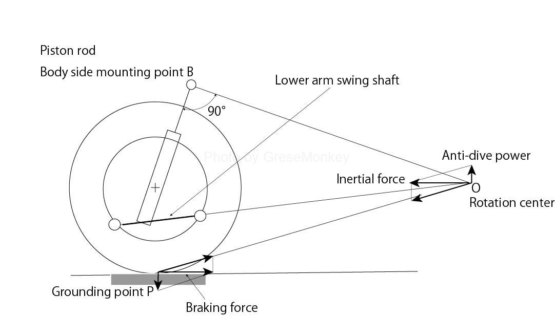
Figure 4: Strut-type anti-dive geometry (when front-wheel drive)
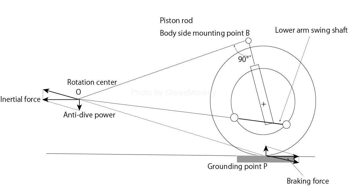
Figure 5: Strut-type anti-dive geometry (when driving rear wheels)
Fig. 4 shows the anti-dive characteristics on the front wheel side that occur during braking, and Fig. 5 shows the anti-lift characteristics on the rear wheel side.
However, in the case of the strut type, the position and inclination of the swing axis of the lower arm can be selected to the same extent as the double wishbone type, but the position of the attachment point on the vehicle body side of the strut is on the layout of the vehicle body. You will be restricted.
For example, the rear struts are tilted backwards to avoid the rear seat back. The mounting position of the front struts is naturally restricted in order to make them proper casters.
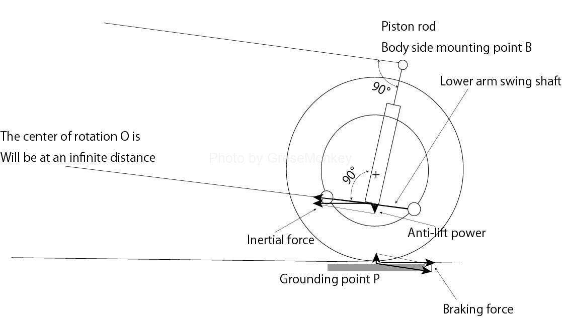
Figure 6: When the center of rotation is at an infinite distance
FIG. 6 shows a case where the strut is tilted backward and the piston rod is perpendicular to the swing axis of the lower arm. That is, the straight line perpendicular to the piston rod is parallel to the coaxial like the lower arm, and the position of the center of rotation O is infinitely distant.
In this case, the effect is slightly inferior to that when the rotation center O is nearby, but the characteristics of anti-lift and anti-squat can be given.
That is, since the wheels are pulled backward during braking, the vehicle body side tries to move forward and downward to generate anti-lift characteristics, and when accelerating, the wheels try to move forward, so the vehicle body side tries to move backward and upward and has anti-squat characteristics. Occurs.
These are examples of the rear wheel side, but similarly, in the case of the front wheel side, the anti-dive characteristic can be given by setting the swing shaft in a forward leaning posture.
Force acting during braking
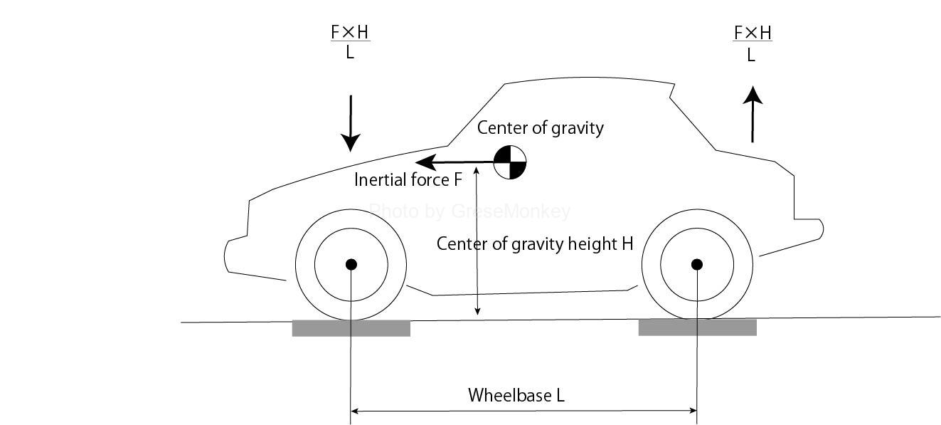
Figure 7: Inertial dive and lift
The front is lowered during braking, and the force to raise the buttocks is generated by applying the inertial force F generated during running to the center of gravity of the vehicle body. (See Figure 7)
The inertial force F has the same magnitude as the braking force F, but this braking force is the sum of the braking forces generated by the front wheels and the rear wheels.
However, the braking force of the front wheels and the rear wheels is not the same, and the front wheels are usually set to be larger in consideration of the load transfer during braking.
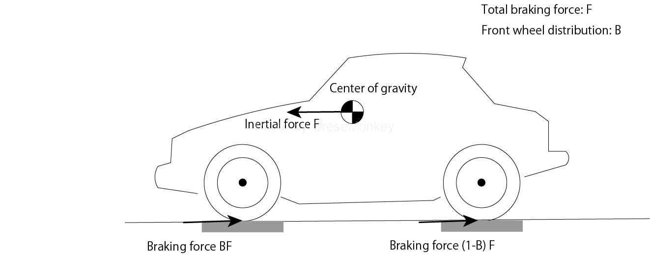
Figure 8: Braking force of front and rear wheels
The distribution of this braking force to the front wheel side is generally about 60% to 70% of the total braking force, but if this braking force is B, the braking force on the front wheel side will be B and F, and the rear wheel side. The braking force of is (1-B) ・ F. (See Figure 8)
Zero nose dive
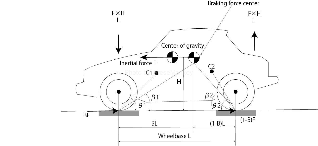
Figure 9: Center of rotation to zero dive and lift
In FIG. 9, assuming that the wheelbase is L and the height of the center of gravity is H, the front wheel side is pushed down by a force of F × H / L, and at the same time, the rear wheel side is tried to be lifted by the same force.
Here, assuming that the angle between the center of rotation of the front wheel side and the road surface is C1 and the rear wheel side is C2 and θ2, respectively, the force to lift the front wheel side generated by the braking force on the front wheel side is B. Since it becomes Ftan θ1, to make the forward downward force (nose dive) zero
$$
\frac{F×H}{L} = BF\tan\theta1
$$
$$
\frac{H}{B×L} = \tan\theta1
$$
Here, assuming that the angle between the center of braking force and the road surface is β1 from Fig. 9,
$$
\frac{H}{B×L} = \tan\beta1 より
$$
$$
∴\tan\beta2 = \tan\theta2
$$
In other words, if the center of rotation C1 is set on a straight line connecting the center of braking force and the ground contact point of the front wheels, the anti-dive geometry will be zero forward descent (zero nose dive).
If θ1 <β1, a nose dive will occur.
Zero tail lift
Figure 9: Center of rotation to zero dive and lift
To reduce the tail lift to zero
$$
\frac{F×H}{L} = (1-B)F\tan\theta2
$$
$$
∴\frac{H}{(1-B)L} = \tan\theta2
$$
That is, if the center of rotation C2 is set on a straight line connecting the center of braking force and the ground contact point of the rear wheel, the anti-lift geometry with zero tail lift is obtained.
As with the nose dive, if θ2 <β2, a tail lift will occur.