Distributive injection pump
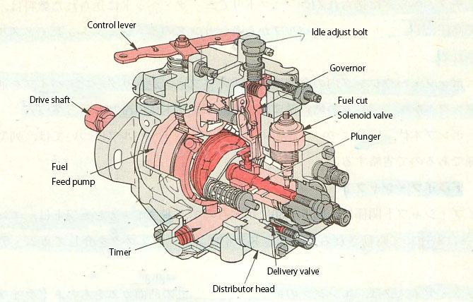
Figure 1: Distributive injection pump
As shown in Fig. 1, the distribution type injection pump has a mechanism to supply fuel to each cylinder by reciprocating while rotating one plunger, and the governor, timer, feed pump, etc. are injection. It is built inside the pump and is smaller, lighter, and faster than the row-type injection pump, so it is often used in vortex chamber engines for small vehicles.
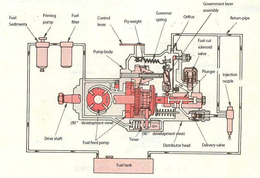
Figure 2: Fuel system for distributed injection pumps
Fig. 2 shows the overall configuration of the fuel system using the distribution type injection pump. The fuel in the fuel tank is removed of water by the fuel segmenter, and impurities are filtered by the fuel filter to filter the injection pump body. It is inhaled from the feed pompini built in, and further pressurized and sent to the distributor head.
The fuel sent to the distributor is made high pressure by the plunger, and is pumped from the delivery valve to the injection nozzle of each cylinder and injected.
On the other hand, the surplus fuel in the pump housing is returned from the orifice to the fuel tank through the return pipe. This fuel cycle also plays the role of cooling the entire pump.
As for the delivery valve, the structure and function are the same as those of the row type injection pump, so refer to the following page.
Table of Contents
- Drive shaft
- Distributor head
- Governor (injection amount control)
- Timer (injection timing control)
- Fuel feed pump
Drive shaft
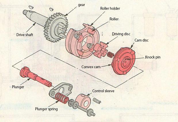
Figure 3: Drive shaft structure
The drive shaft of FIG. 3 is driven at half the rotation speed of the engine, and at the same time drives the cam disc via the driving disc.
This cam disc has the same number of convex cams as the cylinder of the engine, and when driven by the drive shaft, the rollers fixed to the roller holder reciprocate a specified amount of cam lift in the axial direction of the drive shaft.
Further, since the plunger is connected to the cam disc by a knock pin and a plunger spring, the cam disc is reciprocated in the axial direction while rotating with the cam disc.
Distributor head
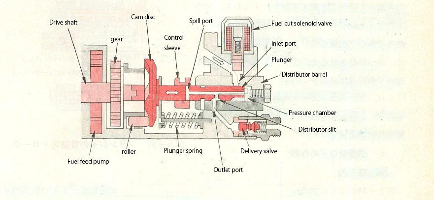
Figure 4: Distributor head
As shown in Fig. 4, the distributor head is composed of a distributor barrel, plunger, control sleeve, delivery valve, etc. that perform light weight, compression, distribution, and pumping in Nanryo.
The distributor barrel is press-fitted into the distributor head and has one inlet port and four outlet ports. (For 4-cylinder engine)
Plunger
The plunger is shown in Fig. 5. In the case of a 4-cylinder engine, four inlet slits, one distributor head, one pressure equalizing slit, and two spill ports are provided, and the plunger rotates in the distributor barrel. While doing reciprocating motion.
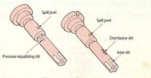
Figure 5: Plunger
- Inlet slit
In the fuel intake stroke, the fuel from the inlet port of the distributor barrel is guided to the pressure chamber.
- Distributor slit
In the Nanryo injection stroke, the fuel pressurized in the pressure chamber is guided to the delivery valve through the outlet port of the distributor barrel.
- Spill port
It serves to release the fuel in the pressure chamber to the pump housing at the end of the fuel injection process.
- Pressure equalizing slit
After the fuel injection is completed, the outlet port and the pump housing are connected, and the high-pressure fuel up to the delivery valve is released to the pump housing to reduce the fuel pressure.
Control of injection amount
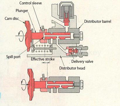
Figure 6: Effective stroke of the plunger
The injection amount is increased or decreased by moving the control sleeve to the left or right as shown in FIG. 6 and changing the effective stroke until the spill port goes out from the inside of the control sleeve.
That is, when the control sleeve is moved to the left side of the figure, the effective stroke of the plunger is shortened and the injection amount is reduced. Conversely, when the control sleeve is moved to the right side, the effective stroke of the plunger is lengthened and the injection amount is increased.
The effective stroke in this case is the stroke of the plunger from the inside of the control sleeve to the outside of the spill port of the plunger.
Plunger operation
- Fuel inhalation stroke
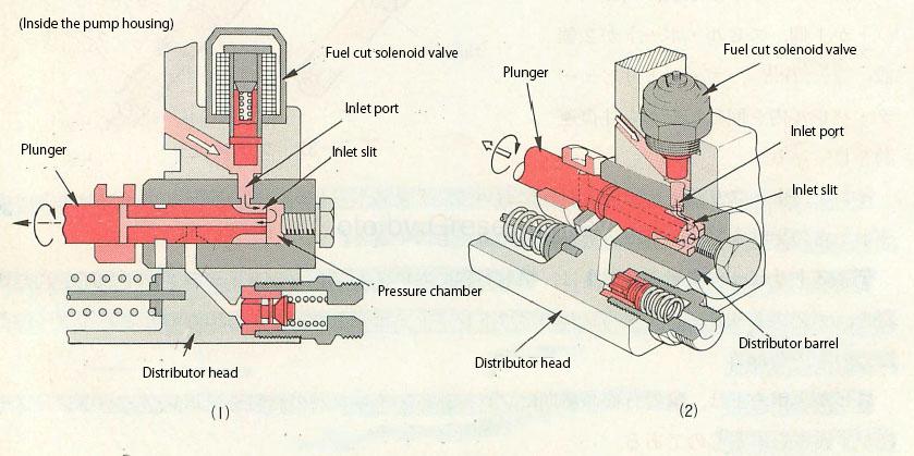
Figure 7: Plunger operation (fuel intake)
From FIG. 7, when the plunger moves to the left while rotating and the inlet port of the distributor barrel and the inlet slit of the plunger overlap each other, the fuel in the pump housing is sucked into the pressure chamber and the plunger.
- Start spraying
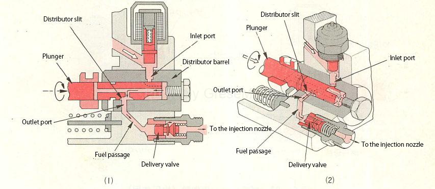
Figure 8: Plunger operation (start of injection)
From Fig. 8, when the plunger moves to the right while rotating, the inlet port closes and fuel compression starts. As it rotates and moves further, the distributor slit of the plunger and the outlet port of the distributor barrel overlap, and fuel is sent from the fuel passage to the injection nozzle via the delivery valve and injected into the cylinder.
- End of injection
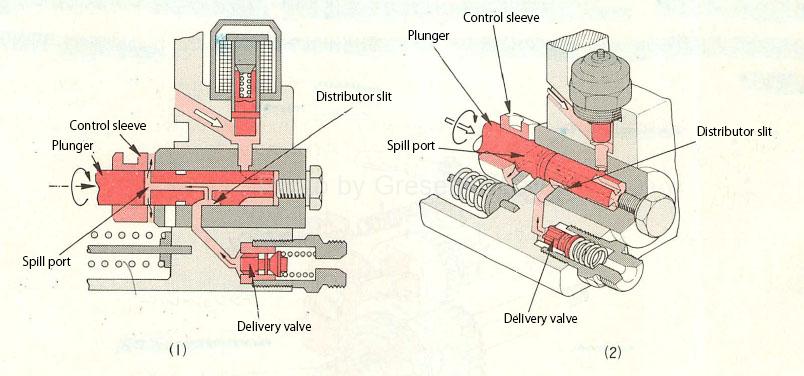
Figure 9: Plunger operation (end of injection)
From Fig. 9, when the plunger moves to the right while opening further, the spill port of the plunger and the inside of the pump housing communicate with each other, so that the fuel in the plunger flows out and the fuel pressure drops, and the fuel is pumped to the injection nozzle. Is over.
Pressure equalizing effect
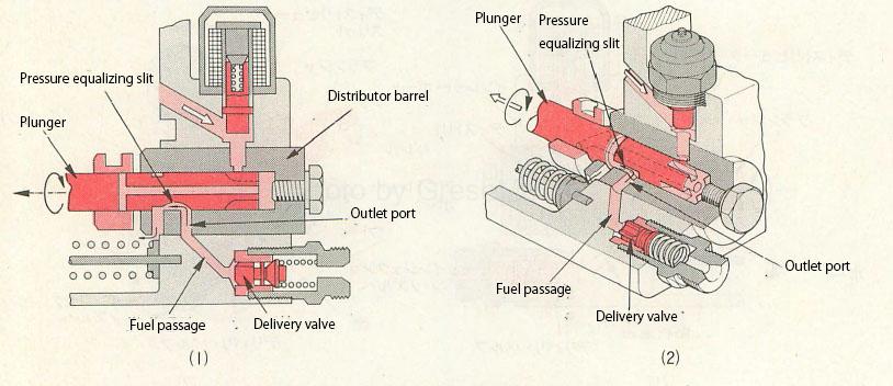
Figure 10: Plunger operation (pressure equalizing action)
When the pressure equalizing slit of the plunger overlaps the outlet port of the distributor barrel while the pumper is rotating and returning to the left as shown in Fig. 10 after the fuel pumping is completed, the pressure in the passage to the delivery valve is increased to the pump housing. The pressure is returned to.
By this process, the pressure difference between the cylinders in front of the injection official residence is eliminated, and stable injection can be obtained.
Governor (injection amount control)
The governor controls the speed according to the load of the engine and automatically controls the injection amount. The functional classification includes all-speed governor, minimum maximum speed governor, and half all-speed governor. ..
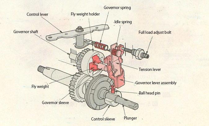
Figure 11: Governor
Fig. 11 shows an example of an all-speed governor. The control lever linked with the accelerator pedal changes the spring force of the governor spring, and the position of the control sleeve is determined in balance with the centrifugal force of the fly weight to control the speed. The operating principle is the same as that of the row type injection pump.
Timer (injection timing control)
The timer controls the injection timing by the fuel pressure according to the rotation speed of the engine.
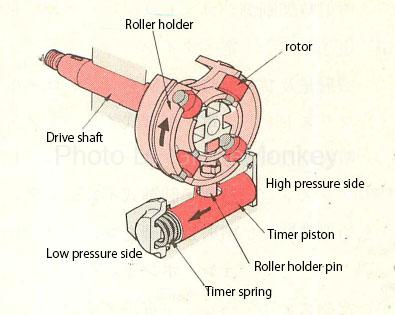
Figure 12: Timer
Figure 12 shows an example of a timer, in which the row-type injection pump uses the balance between the centrifugal force of the fly weight and the spring force of the spring to advance the angle, while the distribution type uses the balance between the fuel pressure and the spring. A hydraulic timer is used in which the timer piston is operated to advance the angle by balancing the spring force.
Fuel feed pump
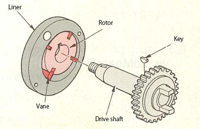
Figure 13: Fuel feed pump
The fuel feed pump is a vane type pump as shown in FIG. 13, and the rotor is driven by a drive shaft.
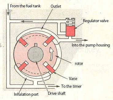
Figure 14: Fuel pumping
From FIG. 14, in the pumping of fuel, when the rotor is rotated by the drive shaft, the vane incorporated in the groove of the rotor pops out due to centrifugal force and rotates along the inner surface of the liner, and the rotor, vane and liner are pumped. The inhalation / delivery action is performed by changing the volume composed of.
In this vane type pump, when the engine tries to rotate in the reverse direction, the fuel suction / delivery action is lost, so that the reverse rotation is prevented.
In addition, the oil supply pressure of the fuel feed pump is controlled within the specified range by the regulator valve.
Figure 2: Fuel system for distributed injection pumps