Electronically controlled injection pump
The electronically controlled injection pump controls the fuel injection amount, injection timing, etc. by a control unit, and the row type and the distribution type are used in combination as follows.
- Row type injection pump
- Combination of fuel injection amount control by control unit
- Electronic governor + mechanical timer
- Electronic timer + mechanical governor
- Pre-stroke electronically controlled injection pump + mechanical governor
- Combination in which the control unit controls the fuel injection amount and injection timing
- Electronic governor + electronic timer
- Pre-stroke electronically controlled injection pump + electronic governor
- Combination of fuel injection amount control by control unit
- Distributive injection pump
- Combination in which the control unit controls the fuel injection amount and injection timing
- Electromagnetic spill valve + electronic timer
- Combination in which the control unit controls the fuel injection amount and injection timing
Here, a system that combines a pre-stroke electronically controlled injection pump and an electronic governor in a row-type injection pump (hereinafter referred to as an electronically controlled injection pump) will be described.

Figure 1: Pre-stroke electronically controlled injection pump + electronic governor
Based on the signals of each sensor that detects the operating state of the engine, the electronically controlled injection pump controls the fuel injection timing with the pre-stroke variable mechanism and the fuel injection amount with the electronic cabana based on the signal from the control unit. There is.
Variable pre-stroke mechanism (control of injection timing)
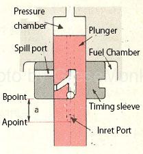
Figure 2: Plunger pre-stroke
The pre-stroke is the cam lift amount (a) from point A at the start of the lift of the plunger to point B at the start of injection when the cam of the injection pump rotates as shown in Fig. 2. In the conventional injection pump, the plunger barrel. The pre-stroke is constant because is fixed, but the electronically controlled injection pump has a variable mechanism that can freely change the position of the timing sleeve, so by moving this position up and down, The injection timing is changed by changing the prestroke.
That is, when the timing sleeve is downward, the prestroke is small and the injection timing is early, and conversely, when the timing sleeve is upward, the prestroke is large and the injection timing is late.
Therefore, the injection timing is controlled by increasing the prestroke in the low / medium speed range of the engine and decreasing it in the high speed range.
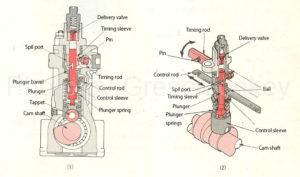
Figure 3: Pump body
In the pre-stroke variable mechanism, a rotatable timing rod is attached in parallel to the upper part of the control rod of the pump body as shown in FIG. In the middle of the plunger barrel, a timing sleeve that can move in the lift direction of the plunger and has a spill port is attached, and a pin of the timing rod is fitted in the groove of the sleeve.
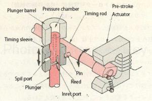
Figure 4: Variable pre-stroke mechanism
Therefore, when the pre-stroke actuator is operated by the signal from the control unit, the rotation of the timing rod is transmitted to the timing sleeve via the pin as shown in FIG. 4, so that the timing sleeve moves up and down and the injection timing changes.
Control of injection amount
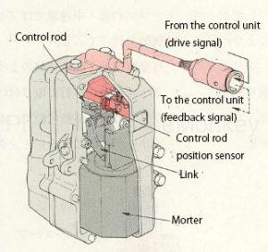
Figure 5: Electronic governor
The injection amount is controlled by an electronic governor operated by a signal from the control unit.
As shown in FIG. 5, the electronic governor is composed of a control rod, a link mechanism, a motor, a control rod position sensor, and the like.
When the motor is operated by a signal from the control unit, the vertical movement of the motor is transmitted to the control rod via the link mechanism, so that the control rod moves left and right and the injection amount increases or decreases.
Sensor
The sensor detects an electric signal according to the operating state of the engine and inputs it to the control unit. Here, the control rod position sensor, pre-stroke position sensor, crank angle sensor, boost pressure sensor, accelerator position sensor and water temperature The sensor will be explained.
Control rod position sensor
The control rod position sensor is attached to the end of the control rod as shown in FIG. 5, and detects the actual control rod position with respect to the target control position instructed by the control unit and inputs it to the control unit.
Pre-stroke position sensor
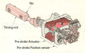
Figure 6: Pre-stroke position sensor
The pre-stroke position sensor is integrally attached to the pre-stroke actuator at the end of the timing rod as shown in Fig. 6, and detects the actual pre-stroke position with respect to the target pre-stroke position instructed by the control unit. Input to the control unit.
Crank angle sensor
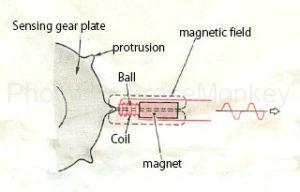
Figure 7: Crank angle sensor
The crank angle sensor detects the rotational speed of the engine and the position of the top dead center of the piston, and generally has two sensors, a main sensor and a sub sensor.
The crank angle sensor is a pickup coil type as shown in Fig. 7, and is composed of a coil, pole, magnet, etc. When the sensing gear plate rotates, the gap between the protrusion of the plate and the tip of the pole changes, and the pickup coil A voltage is generated in the pickup coil because the magnetic field of the pickup coil changes.
This voltage is input to the control unit as the engine speed and top dead center position signal of the piston.
Boost pressure sensor
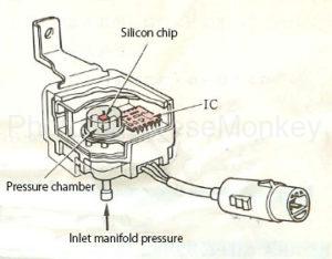
Figure 8: Boost pressure sensor
The boost pressure sensor measures the pressure inside the inlet manifold. As shown in Fig. 8, it is a pressure sensor that uses a semiconductor that changes its electrical resistance when pressure is applied to the silicon chip, and measures the inlet manifold pressure. Input to the control unit as an electric signal. (Inlet manifold pressure = negative pressure)
Accelerator position sensor
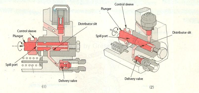
Figure 9: Accelerator position sensor
The accelerator position sensor detects the opening degree of the accelerator pedal and inputs it to the control unit, and is provided in the accelerator pedal portion as shown in FIG.
When the accelerator pedal is depressed, the variable resistance of the accelerator position sensor changes, and a voltage corresponding to the amount of depression of the pedal is generated. This voltage is input to the control unit as an accelerator position signal.
Water temperature sensor
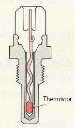
Figure 10: Water temperature sensor
The water temperature sensor detects the temperature of the cooling water of the engine, and is attached to the water jacket of the cylinder block, etc., and has a built-in thermistor whose resistance value changes greatly depending on the temperature as shown in FIG.
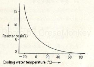
Figure 11: Thermistor resistance characteristics
FIG. 11 is a graph of the resistance value characteristics of the thermistor, and the resistance value of the thermistor decreases as the cooling water temperature increases.
Therefore, the water temperature sensor converts the change in the cooling water temperature into the resistance value of the thermistor and inputs this as a signal to the control unit.
control unit
The control unit determines the fuel injection amount and injection timing suitable for the operating condition of the engine based on the signals from each sensor, and notifies the abnormal system when an abnormality occurs in the signal system from the angle sensor. It is equipped with a self-diagnosis system and a fail-safe function to avoid danger.