Car lighting device
A lighting device is indispensable for driving a car safely. This lighting device is used for purposes such as lighting, signs and signals, and is composed of switches, lamp assemblies and wiring.
For each purpose, there are luminosities and colors regulated by law.
In addition, since stop lamps, tail lamps, turn signal lamps, etc. are installed at the rear of the car, a combination lamp that combines each lamp into one is used from the viewpoint of simplification of the lamp assembly and design. There is.
Table of Contents
Light bulb (bulb)
As shown in Fig. 1, a bulb is generally provided with a filament as a light source inside a glass sphere, which is filled with a mixture of nitrogen gas and an inert gas such as argon gas, and a bulb with a mouthpiece is used. ..
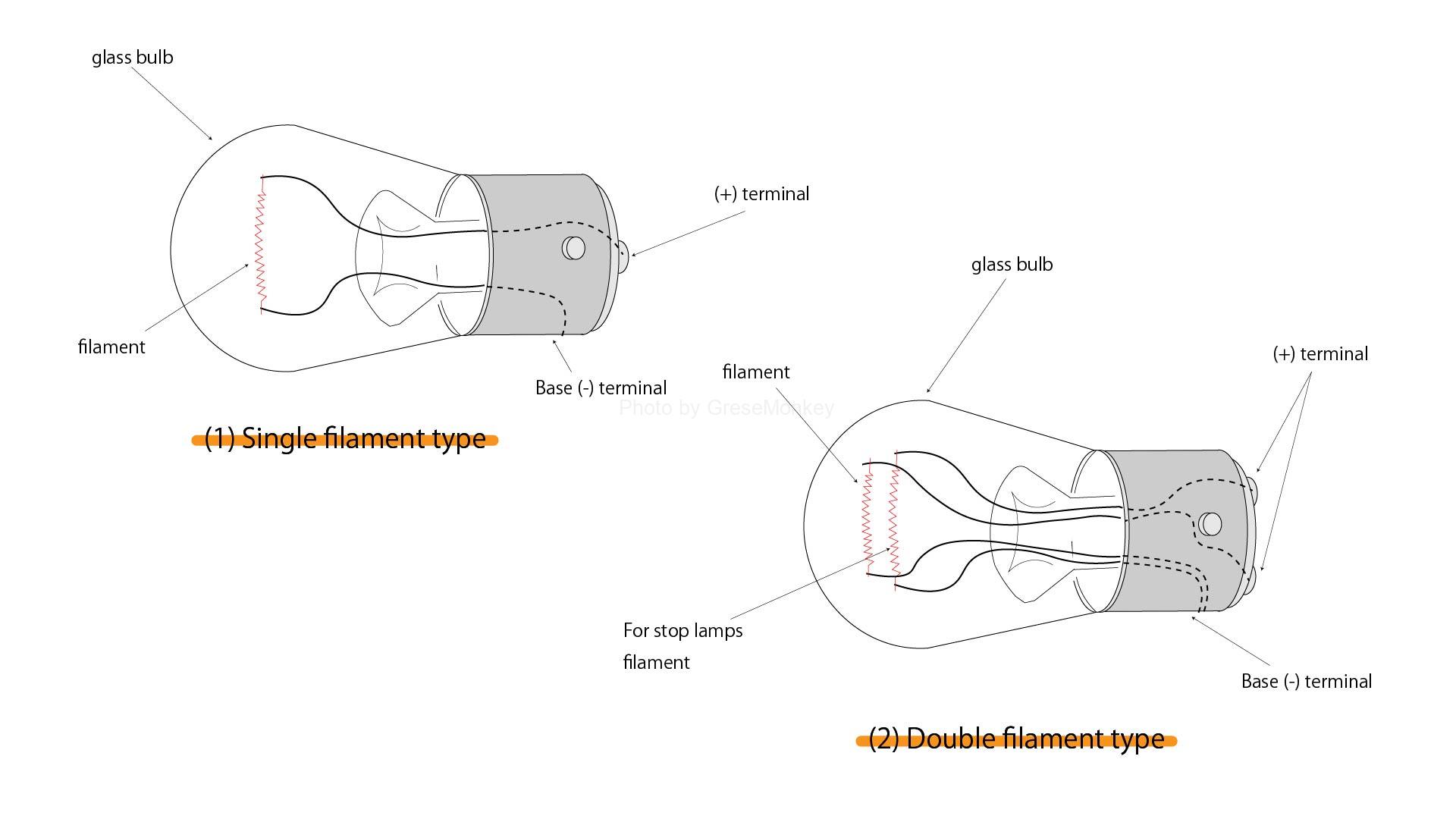
Figure 1: Single valve and double valve
There are single filament filaments as shown in Fig. 1 (1) and double filament filaments as shown in Fig. 1 (2), which are used according to the purpose.
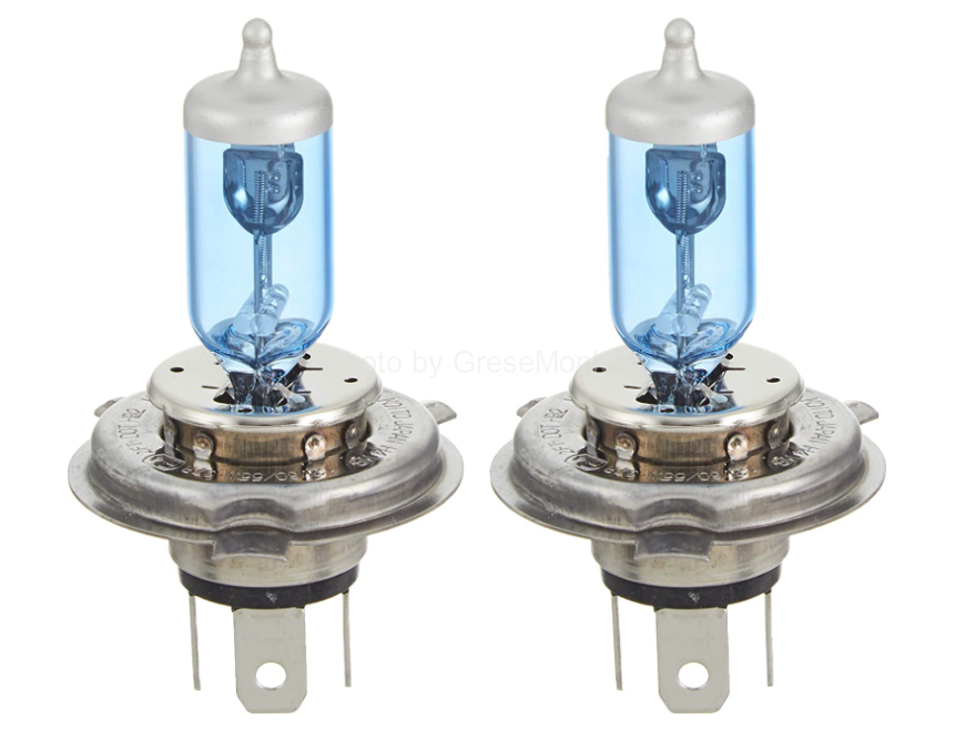
In addition, halogen lamps that use an enclosed gas in which xenon gas or krypton gas is added to iodine are used for headlamps (Fig. 2).
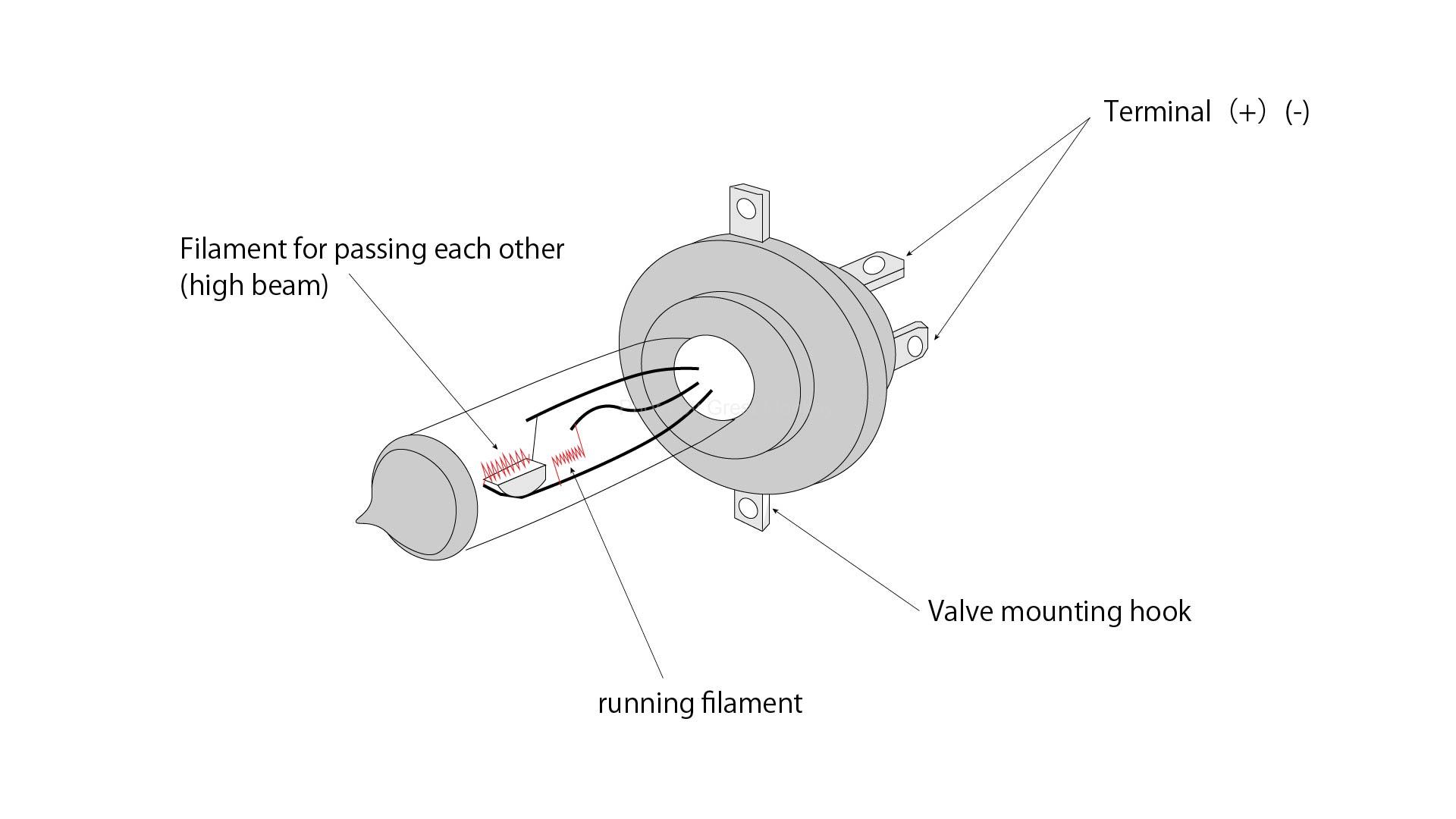
Figure 2: H4 type halogen lamp
Compared to ordinary gas-filled bulbs, this bulb is brighter with the same capacity, has a longer life, and has stable luminosity. In addition, filamentless discharge tube type headlamps filled with xenon gas, which consumes less power than halogen lamps and doubling the amount of light, are also used in some cases.
In modern automobiles, most of the bulbs and headlamps are LED lamps (light emitting diodes). We will focus on bulbs and headlamps before LEDs became mainstream.
head lamp
Headlamp structure
Here, we will focus on the sealed beam type headlamp, which is the prototype of the headlamp, and the semi-shielded beam type headlamp, which is generally used.
In either case, the light emitted from the filament is reflected directly or by a reflector, passes through the lens, and is projected forward.
Reflectors are generally made of metal or glass material and are shaped like a rotating paraboloid. If the parallel light rays reflected by the reflector are irradiated as they are, it will give glare to the oncoming vehicle when they pass each other. , The optical axis is adjusted so as not to give glare to oncoming vehicles.
In addition, various lens shapes are adopted depending on the vehicle model.
- Sealed beam type
As shown in Fig. 4, the entire unit of the sealed beam type headlamp is a light bulb, and the reflector has an aluminum plating on the glass surface.
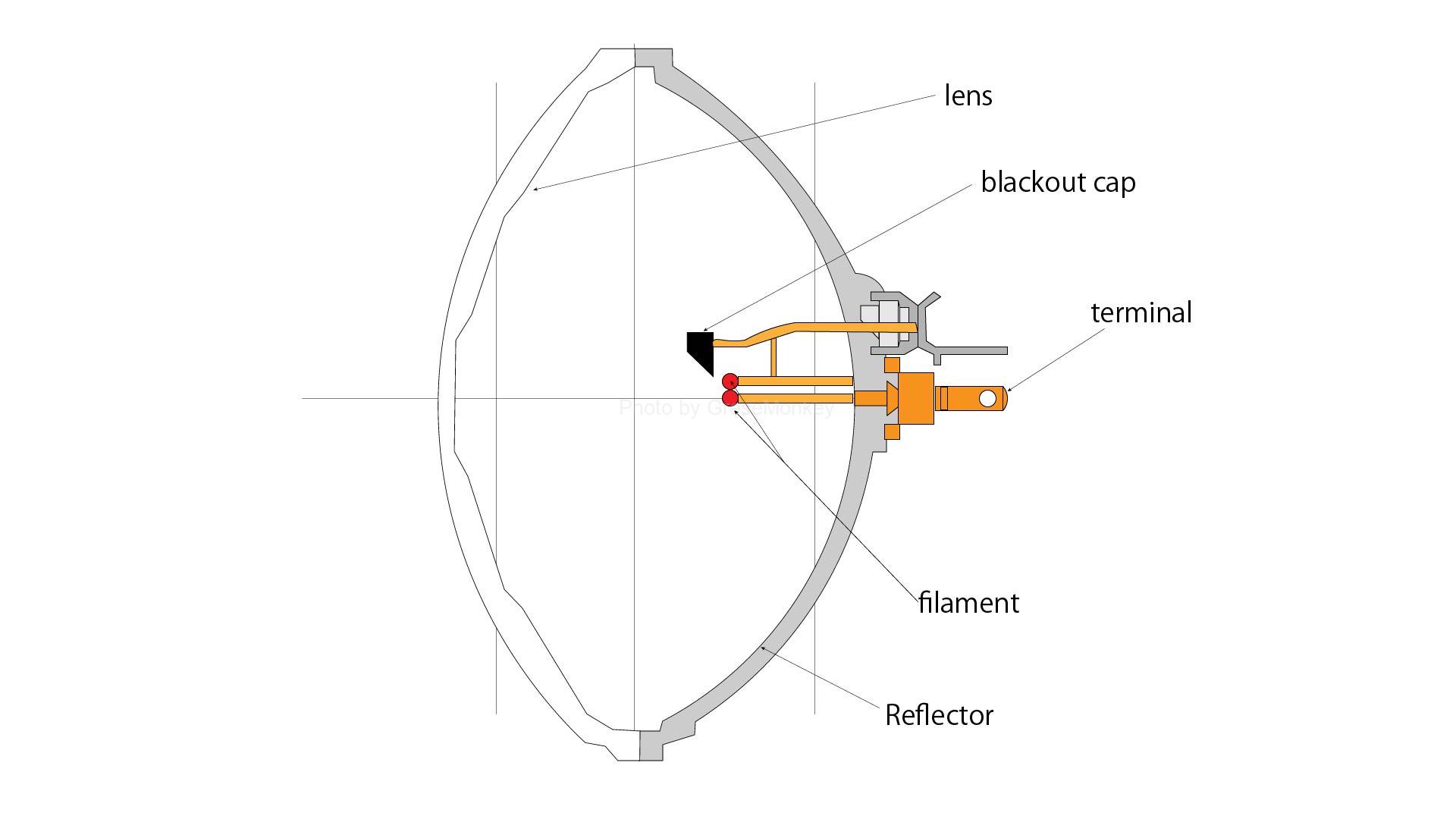
Figure 4: Sealed beam headlamp
A light-shielding cap is installed above the filament to block the light directly shining upward from the filament, prevent diffused reflection by water droplets and snowflakes in bad weather such as rain, snow and fog, and prevent the front visibility from getting worse. Has been done.
- Semi-sealed beam type
As shown in Fig. 5, the semi-sealed beam type headlamp has a lens and a reflector integrated.
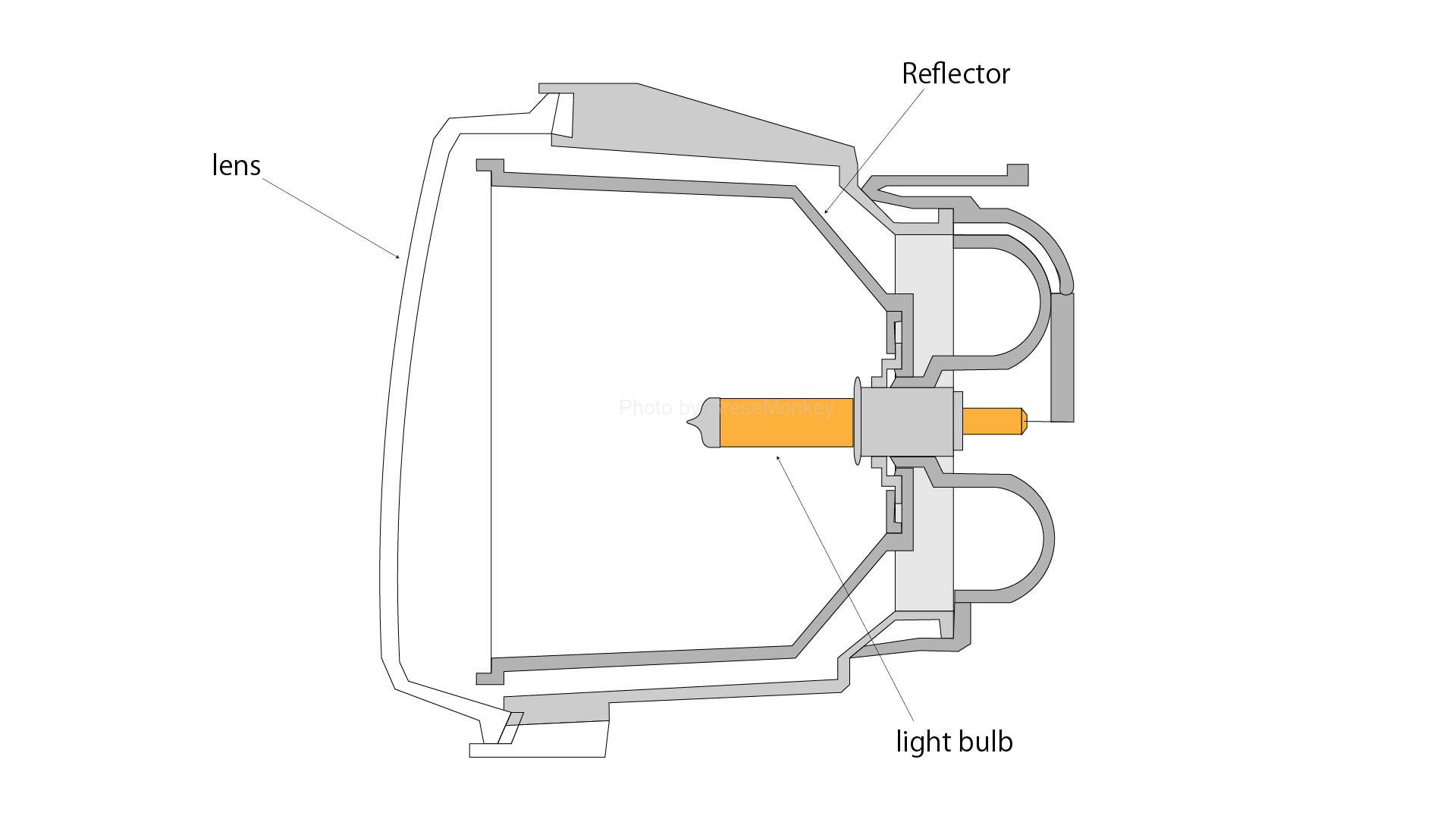
Figure 5: Semi-shielded headlamp
The valves are designed to be installed independently and can be replaced from the rear. Halogen lamps are used for the bulbs.
Headlamp function
The purpose of headlamps is to illuminate the front at night, and the light distribution characteristics are important in terms of functionality because they must not give glare to oncoming vehicles when they pass each other. In other words, how the light is diffused and irradiated.
The headlamp has a flat light distribution characteristic that is wide horizontally and narrow in the vertical direction due to its use, and its brightness is weak at both ends and becomes stronger toward the center. In addition, these light distribution characteristics can be changed according to the conditions when traveling and when passing each other.
- 2-lamp sealed beam type headlamp
As shown in Fig. 6, the two-lamp sealed beam type headlamp has two filaments in one unit.
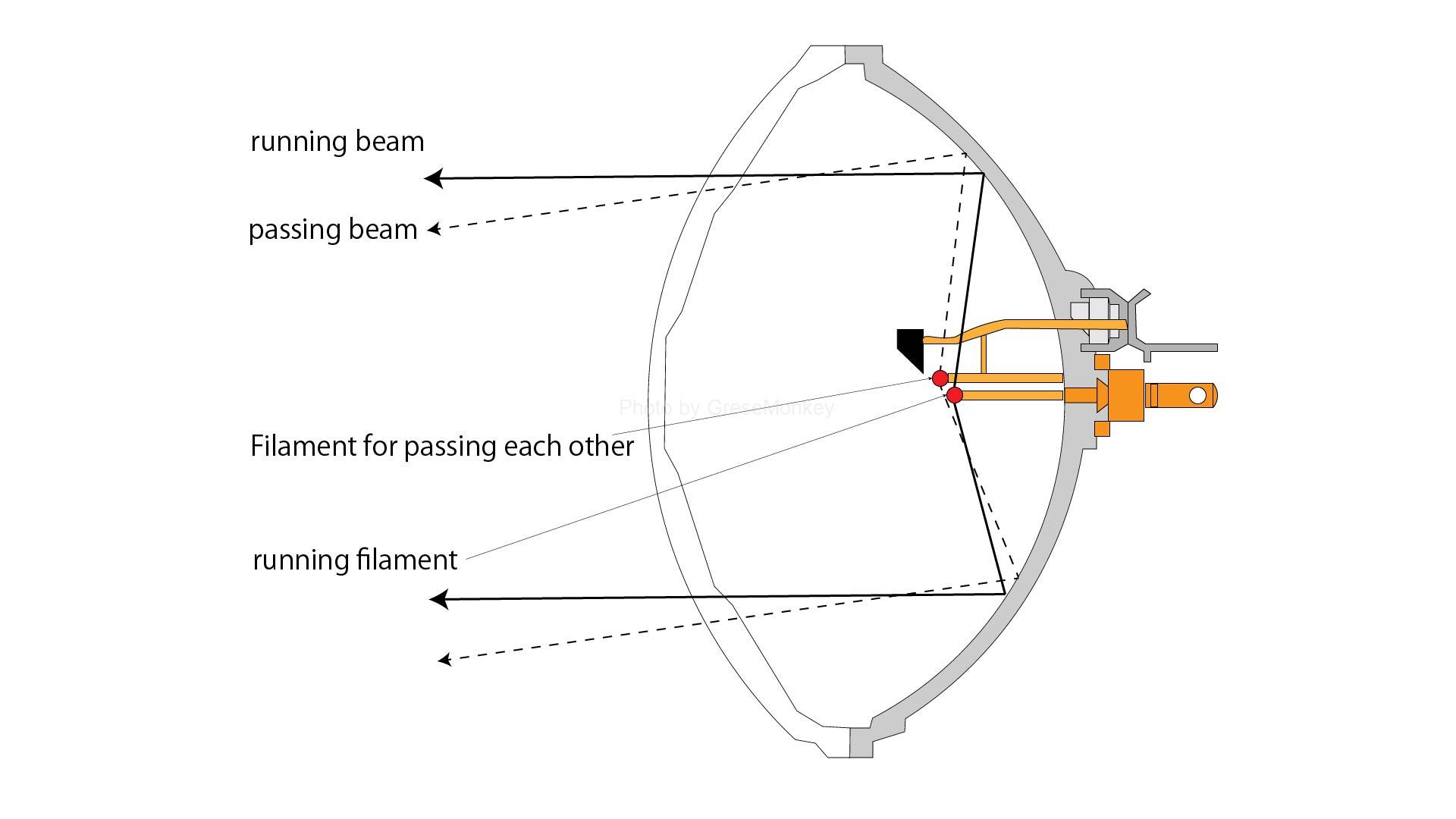
Figure 6: Dual sealed beam headlamp
When one filament (for traveling beam) is placed at the focal point of the reflecting mirror and a current is passed through the filament, the light of the filament becomes a parallel ray by the reflecting mirror and irradiates a long distance.
The other filament (for the passing beam) is located slightly above the focal point.
When the filament for the passing beam is switched with the changeover switch, the position of the light source is raised, so that the light flux illuminates in the downward direction and slightly to the left (opposite direction of the oncoming vehicle) due to the nature of reflection.
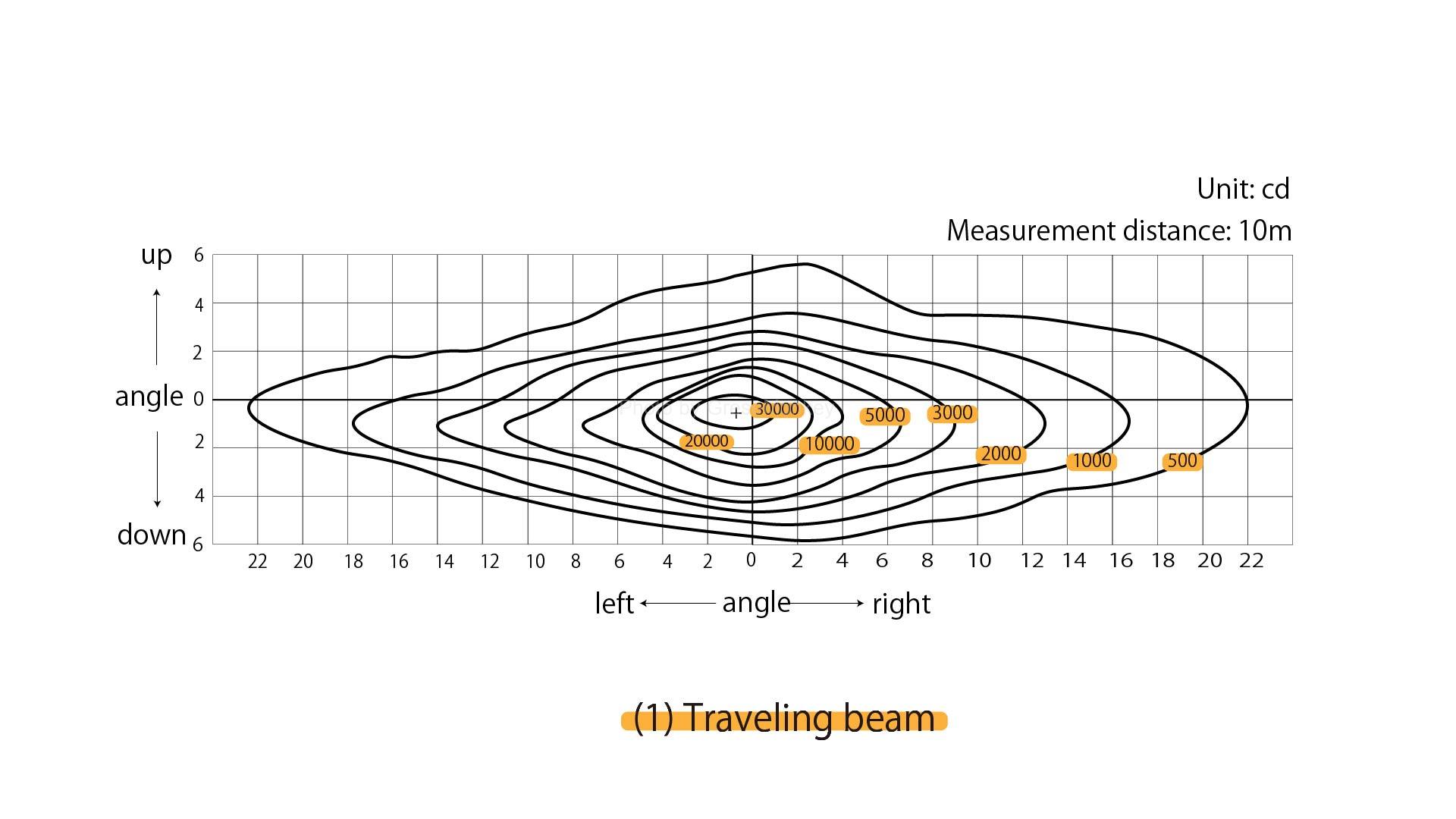
Figure 7(1): Light distribution characteristics of dual sealed beam headlamp (driving beam)
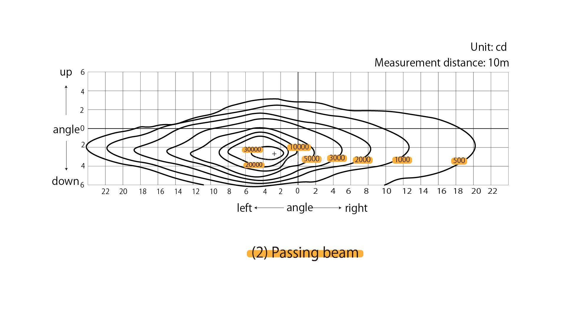
Figure 7(2): Light distribution characteristics of dual sealed beam headlamp (passing beam)
- 2-lamp semi-sealed beam type headlamp
In the two-lamp semi-sealed beam type headlamp (halogen lamp), as shown in Fig. 8, the passing filament is arranged in front of the focal point, and a light-shielding plate is provided under the filament.
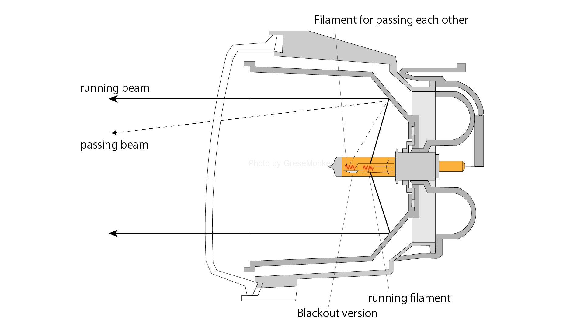
Figure 8: Dual semi-shielded beam halogen headlamp
For this reason, as shown in Fig. 9 (1), when the traveling beam is used, the irradiation is performed up to the top, but when the beam is passing, the irradiation on the left and right is cut almost horizontally as shown in Fig. 9 (2), and they pass each other. It reduces the glare of oncoming vehicles at times.
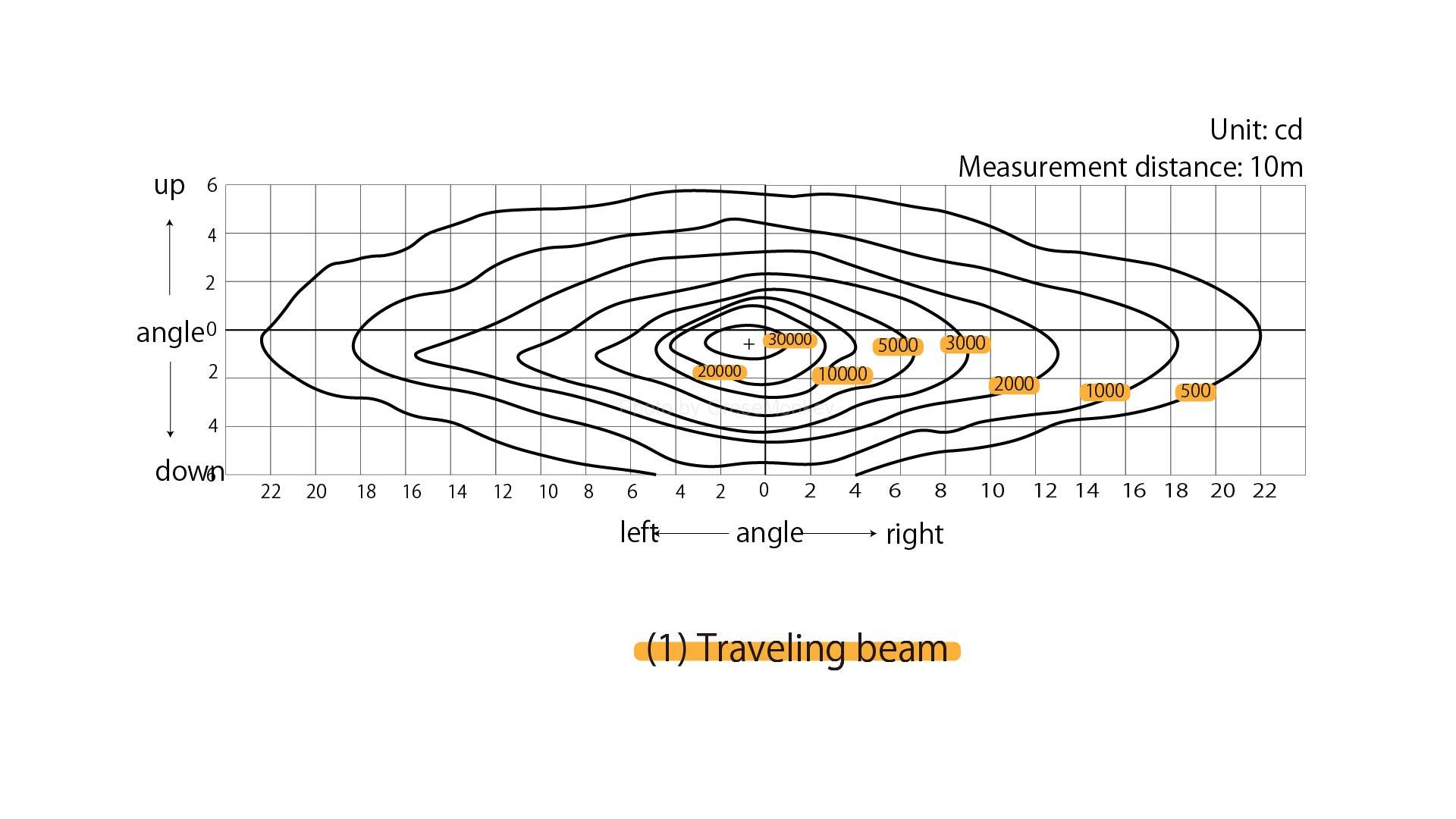
Figure 9(1): Light distribution characteristics of dual semi-shielded beam halogen headlamp (driving beam)
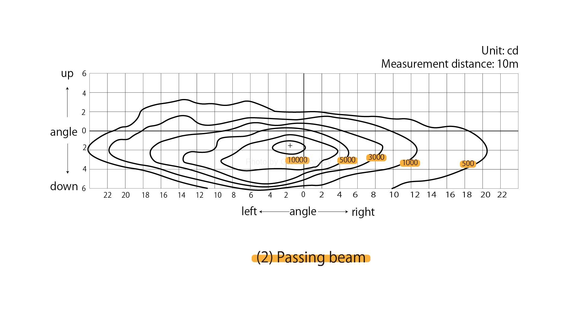
Figure 9(2): Light distribution characteristics of dual semi-shielded beam halogen headlamp (passing beam)
- Lighting circuit
FIG. 10 is an example of a lighting circuit. To operate this circuit, when the light control switch is set to “T”, the tail lamp relay is turned on, and the tail lamp, clearance lamp, and license lamp are lit.
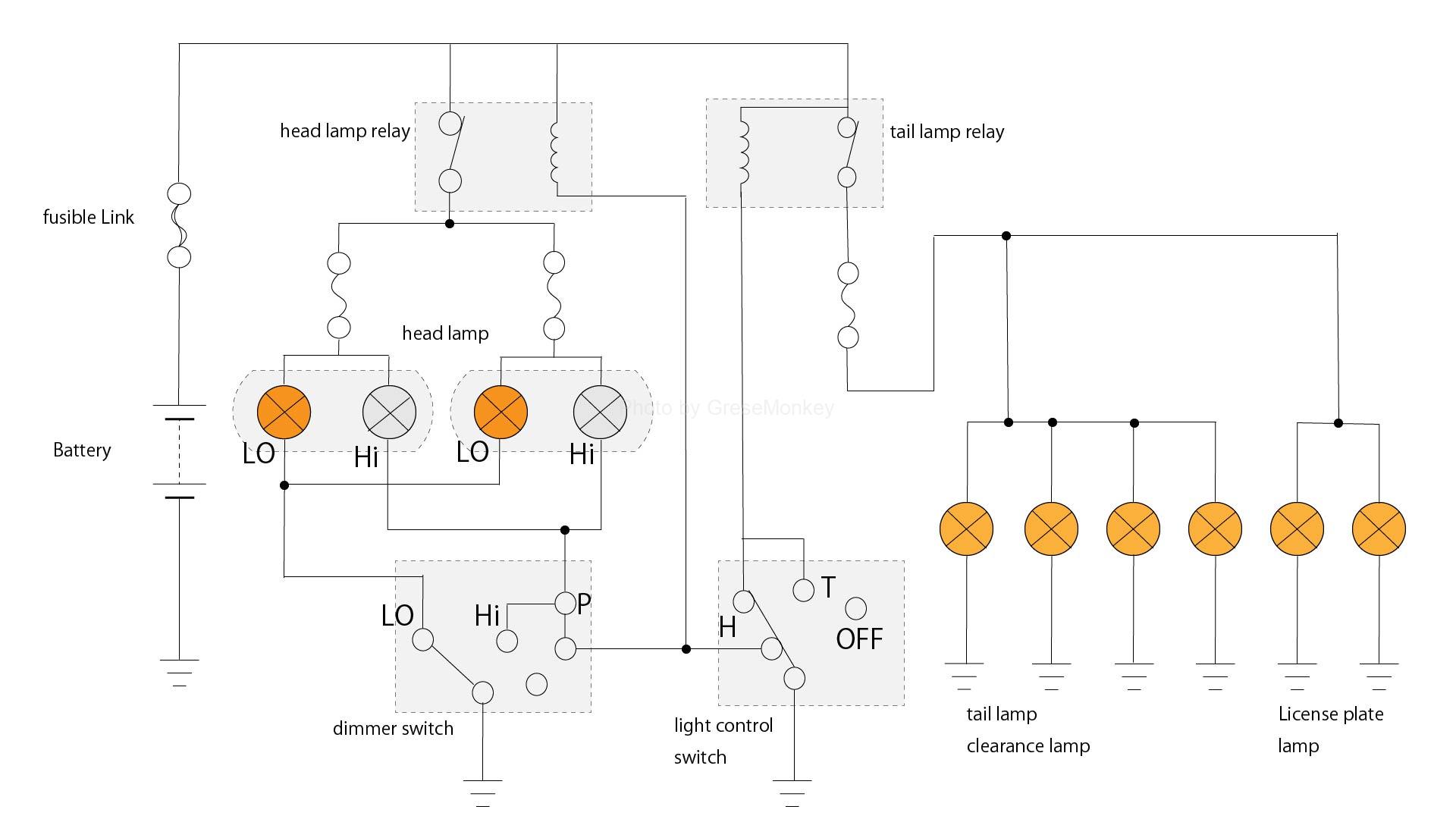
Figure 10: Light circuit
Next, when the switch is set to “H”, the headlamp relay turns on and the headlamp lights up at the same time.
In addition, the direction and distance illuminated by the headlamps are switched by the dima switch when traveling and when passing each other.
tail lamp
The tail lamp is often used as a stop lamp because the lighting color is the same, and a double filament type bulb having a filament corresponding to each brightness is often used.
As an electric circuit, as shown in Fig. 10, it can be turned on and off by operating the light control switch through the tail lamp relay.
Figure 10: Light circuit
The red lens is determined by the “Safety Standards for Road Transport Vehicles”.
Stop lamp
The stop lamp is often used as a tail lamp because of the color of the light. Therefore, its type and structure are the same as the tail lamp except for the high mount stop lamp.
Since the stop lamp calls attention to the rear of the vehicle when operating the main brake device and the auxiliary brake device, the stop lamp is lit in conjunction with the brake device.
Therefore, in general, a stop lamp switch as shown in FIG. 11 is attached to the brake device, and its electric circuit is as shown in FIG.
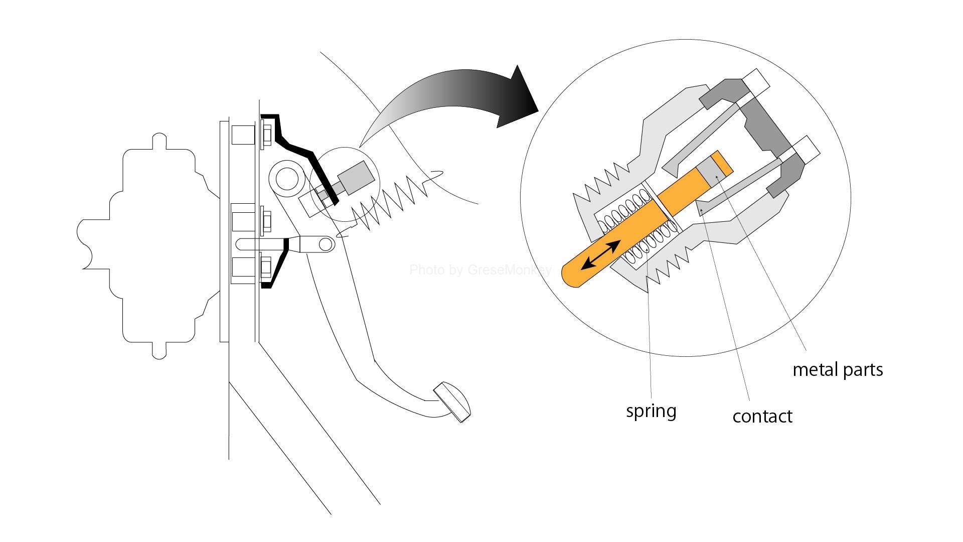
Figure 11: Stop lamp switch
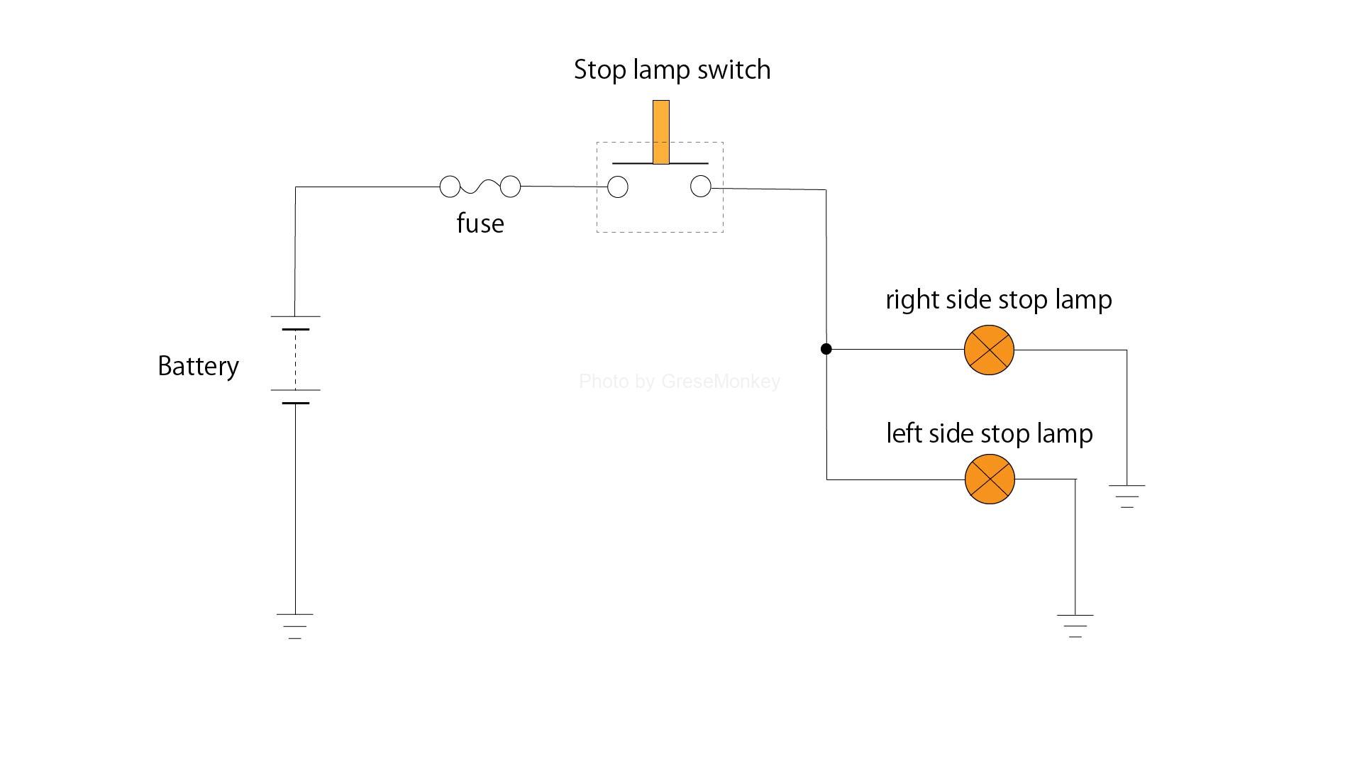
Figure 12: Stop lamp circuit
When the brake pedal is depressed for braking, the brake pedal advances, so that the rod in the switch is pushed out by the spring, the contact comes into contact with the metal portion from the insulating portion, and the lamp lights up.
Back lamp
Some back lamps are used as combination lamps by incorporating them together with other lights, and some are attached to the rear bumper or frame by a bracket that is independent of the other lights. ..
This lamp is lit when the shift lever of the transmission is operated backward. In the manual transmission, a switch is provided in the transmission as shown in Fig. 13, and its electric circuit is as shown in Fig. 14. It has become.
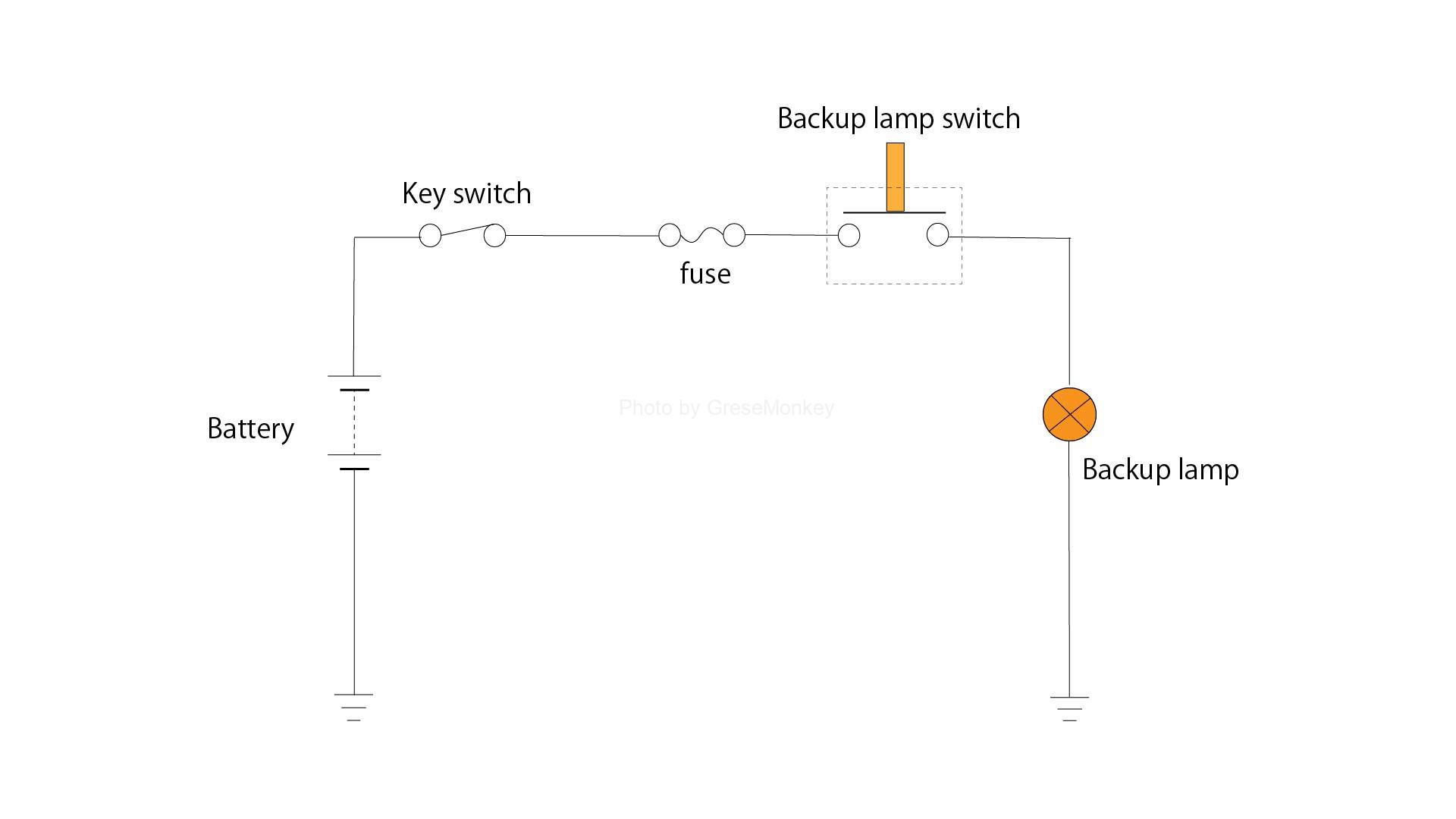
Figure 14: Back lamp circuit
When the shift lever is operated backward, the switch is pushed by the shift fork, the circuit turns on in FIG. 14, and the lamp lights up. If the shift lever is in a position other than the retracted position, the switch is turned off and the lamp does not light.
Further, in an automatic transmission, when the shift lever is operated in the reverse range, the backward light circuit is turned on by the inhibitor switch (range positioning switch) and the lamp is turned on.
Number lamp
For the number lamp, either the method of illuminating from the top or bottom or the left and right of the number plate is used depending on the position of the number plate (license plate), the shape of the car, etc., but in any case, it is easy to check the license plate. Therefore, the light does not leak to the rear of the car.
Figure 10: Light circuit
The number lamp is connected in parallel with the tail lamp circuit as shown in FIG. 10 so that it can be turned on in conjunction with the tail lamp.
Turn signal lamp
Turn signal lamps and flasher lamps (turn signals) notify other vehicles and pedestrians of the direction by blinking the lamps when changing the direction of travel of the vehicle, so their operation is surely performed and confirmation It must be easy.
Therefore, the following properties are required.
- Abnormal operation can be confirmed in the driver’s seat.
- The blinking cycle should be a cycle suitable for confirmation from the outside.
The turn signal flasher unit that performs this blinking operation is divided into IC type, transistor type, capacitor relay type, etc. from the viewpoint of the operating principle, but since IC type is often used, the IC type will be described.
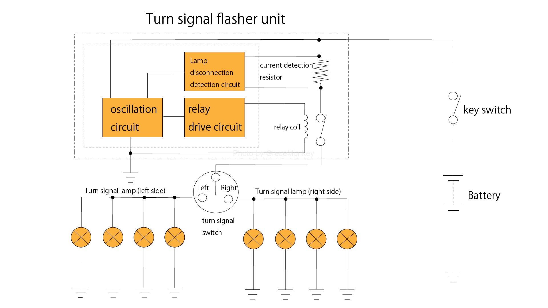
Figure 15: IC turn signal flasher circuit
As shown in Fig. 15, the IC type is a combination of an IC that controls the blinking of the turn signal lamp and a relay. The inside of the IC is roughly divided into an oscillation circuit, a relay drive circuit, and a lamp disconnection detection circuit.
The blinking circuit of the lamp is determined by the oscillation circuit. The signal of the oscillating circuit is added to the relay drive circuit, and the turn signal lamp blinks by controlling the energization and de-energization of the relay coil.
If one of the signal lamp bulbs is disconnected, the current passing through the current detection resistor in the unit will decrease. The change in current at this time is replaced with the change in voltage due to the resistor, and the lamp is detected by the disconnection detection circuit. By sending this detection signal to the oscillation circuit, the number of blinks is increased, and the driver is notified of the disconnection of the lamp.
Hazard lamp
The hazard lamp blinks the front, rear, left, and right signal lamps at the same time in the event of a road failure to indicate that the vehicle is stopped or to warn, and also serves as a turn signal lamp.
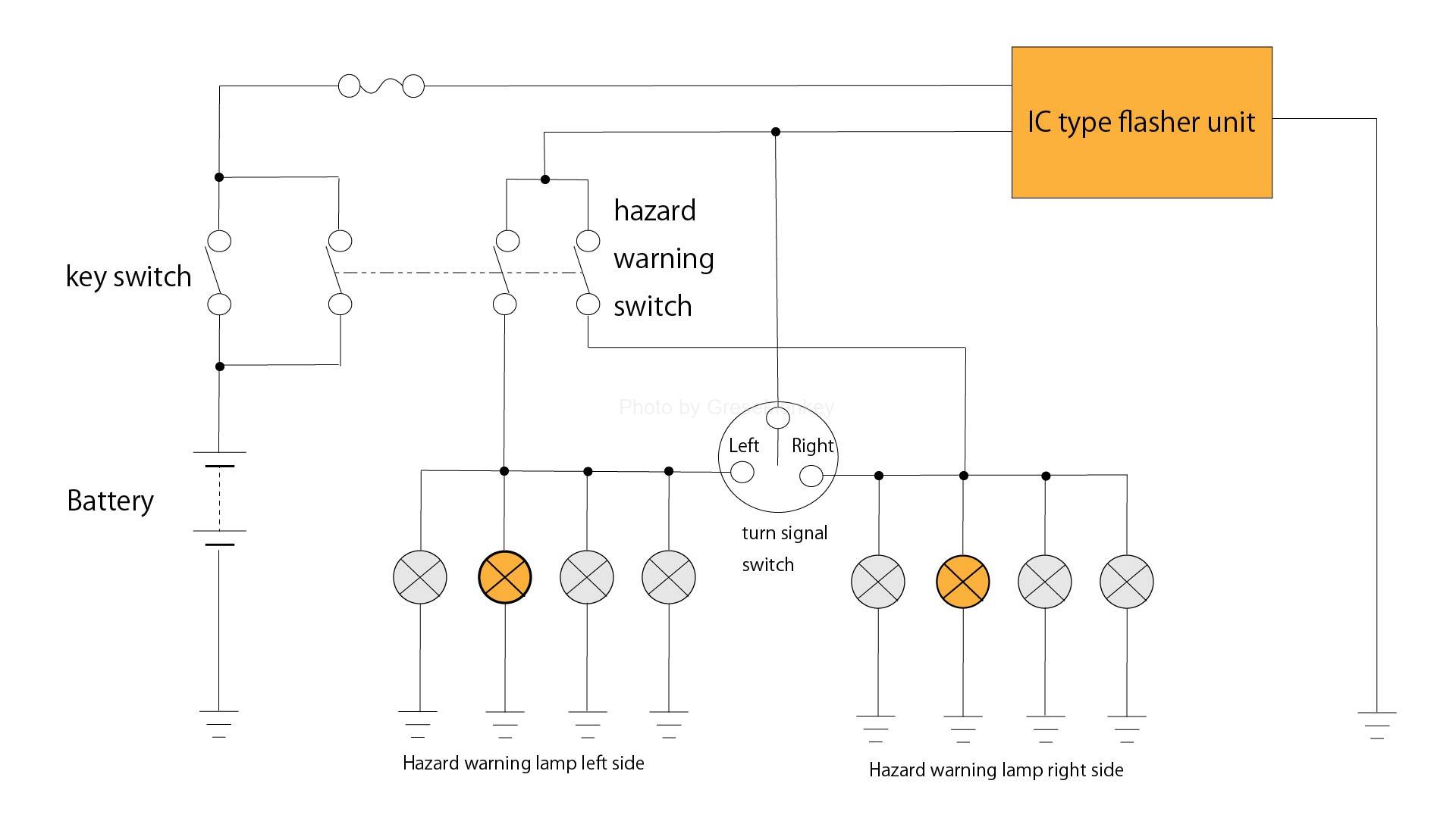
Figure 16: Hazard warning lamp circuit
Therefore, as shown in FIG. 16, a hazard warning switch is provided in the circuit of the turn signal flasher, and the flasher unit is also used.
The difference from the turn signal flasher is that even if the bulb is broken, the number of blinks does not change in order to maintain the display function in the event of a road failure.