Clutch
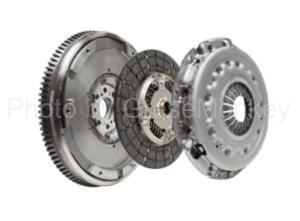
Table of Contents
About the Clutch
When starting the engine of an automobile, the load applied to the engine must be minimized. Specifically, the load from the transmission, which is always connected to the engine, is reduced to zero. The mechanism is such that the load is zeroed and the engine is started.
In addition, by disengaging the clutch during manual transmission shift changes, the load on both the engine and transmission is reduced to zero, enabling smooth gear changes.
A clutch is a device that plays a role of interrupting the load applied to the engine as necessary when transmitting or disconnecting the power of the engine to the transmission.
If the power of the rotating engine is suddenly transmitted while the car is stopped, the car will start suddenly if the power is large, and the rotation of the engine will not be transmitted if the power is small. The car does not move. Therefore, it becomes necessary to manually operate the clutch to gradually connect the power of the engine. The state of the clutch at this time is called half-clutch.
A clutch is installed between an engine and a transmission, and uses friction and oil pressure to transmit the power of the engine. It is necessary that the heat dissipation property to dissipate frictional heat is excellent.
Such a mechanical friction clutch is composed of an operation mechanism that transmits the driver’s operation force using mechanical wires or a hydraulic system, and a clutch body that receives the force and interrupts power transmission. .
Performance required for clutch
The performance required for the clutch includes the following elements.
- The structure shall allow easy and reliable operation such as disconnection and connection of power, half-clutch, etc.
- Appropriate transmission torque capacity.
- It should have sufficient heat absorbing and dissipating ability for the amount of heat generated by the friction of the clutch so that the temperature does not rise excessively.
- The inertial force of the clutch disc should be as small as possible to facilitate shifting of transmission gears. (In order to reduce the inertia force, the weight of the clutch disc should be made as small as possible.
Transmission torque capacity
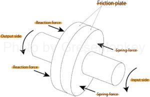
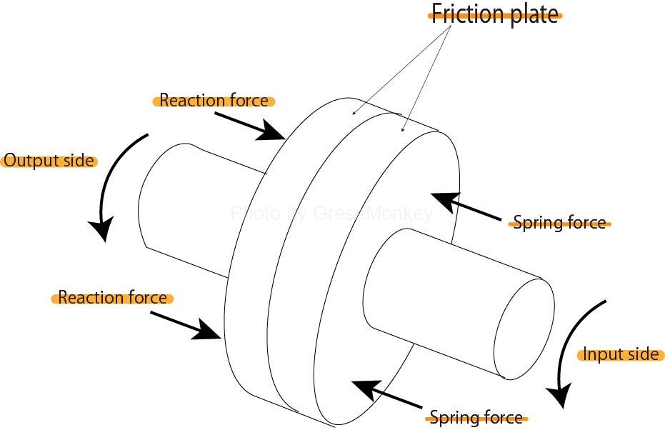
Figure 1: Clutch principle
As shown in Fig. 1, the general structure of a clutch is a structure in which two friction plates face each other and are pressed against each other by the spring force of a spring.
Let T [N·m {kgf·m}] be the torque transmitted from the input side to the output side through this clutch by the pressing force of the spring and the frictional force of the clutch plate.
Then, the maximum value of this T[N·m {kgf·m}] is the maximum capacity of the clutch and represents the transmission torque capacity. This capacity is related to the pressing force of the spring, the friction coefficient of the clutch plate, and the friction area.
If the transmission torque capacity of the clutch is excessively large compared to the torque of the engine, the operation of the clutch becomes difficult, the engagement tends to be abrupt, and the engine tends to stop. Also, if the clutch is suddenly engaged, the greater the transmission torque capacity of the clutch, the greater the impulsive load torque generated in the power transmission system such as the transmission, propeller shaft, and drive shaft. It is desirable for the clutch transmission torque capacity to be smaller than the torque of the engine for the protection of parts.
However, if the transmission torque capacity of the clutch is too small, although the connection becomes smooth, the clutch slips and heat generation increases, and the amount of wear on the surface (facing) of the clutch tends to increase rapidly. In addition, when the temperature rises and the frictional force decreases, the slippage of the clutch increases even more.
For this reason, the transmission torque capacity of the clutch is generally set to 1.2 to 1.5 times the maximum torque of the engine, taking into consideration the maximum torque of the engine and the type and structure of the vehicle. (This is called margin factor.)
Therefore, the margin factor is set larger for large vehicles such as buses and trucks than for passenger cars. (The margin factor is larger for diesel engines than for gasoline engines.)
About the clutch spring
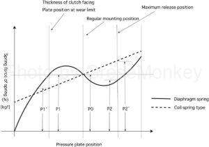
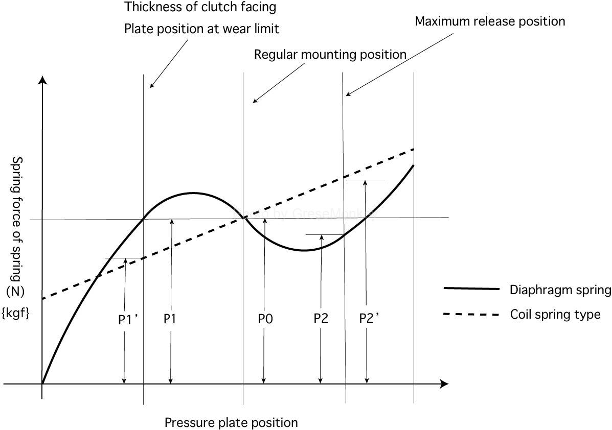
Figure 2: Clutch spring characteristics
There are two types of clutch springs: a coil spring type and a diaphragm spring type. The coil spring system is used in large vehicles such as buses and trucks, while the diaphragm spring system is used in passenger cars.
Fig. 2 shows the characteristics of the clutch springs of the coil spring type and the diaphragm spring type. The solid line in the figure is the characteristic of the diaphragm spring system, and the dotted line is the characteristic of the coil spring system.
In Fig. 2, if the spring force (P0) of both is the same in the regular mounting position (with the clutch pedal released), the maximum release position (the position when the clutch pedal is fully depressed) In the case of the coil spring system, the spring force is P2′, while in the diaphragm spring system, the force is P2, which is smaller than that. It becomes smaller by the difference in spring force.
On the other hand, when the clutch facing wears to the limit, the spring force decreases from P0 to P1′ in the case of the coil spring method, while P0 and P1 are the same in the diaphragm spring method.
From the above, the features of the diaphragm spring system are as follows.
- There is little change in spring force due to wear of the clutch disc.
- When rotating at high speed, there is little decrease in spring force due to centrifugal force.
- The spring force acting on the pressure plate is uniform.
It can be said that the diaphragm spring system enables stable clutch operation without being affected by wear of the clutch disc or driving conditions.
clutch body
Diaphragm spring type clutch
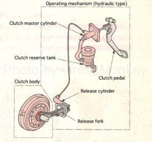
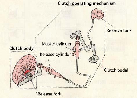
Figure 3: Diaphragm spring clutch
FIG. 3 shows a device for a diaphragm spring type clutch, which is roughly divided into a clutch main body and a clutch operating mechanism.
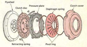
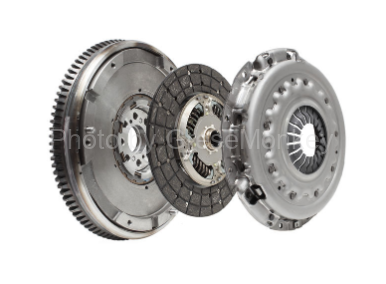
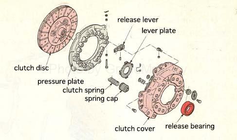
Figure 4: Clutch body components
The clutch body is constructed as shown in FIG.
- Flywheel
- Clutch disc
- Pressure plate
- Diaphragm spring
- Clutch cover
When replacing the clutch, it is normal to order and replace parts 3 to 5 as a clutch cover assembly as an integrated part. The 2 clutch disc is ordered separately from the clutch cover as one part, but it is rare to replace only the clutch disc. It is almost always the case to replace both at the same time.
In other words, if slipping occurs due to wear or malfunction of the clutch disc and it is necessary to replace it, it is possible that the diaphragm spring in the clutch cover assembly may have deteriorated or worn out, or other parts may have deteriorated or worn out. You will have to replace both at the same time.
Also, when replacing the clutch, wear of the flywheel attached to the engine side is also considered, so if there is a problem as a result of the inspection, it is necessary to replace it each time.
About the features and properties of the parts that make up the clutch body
The clutch cover is made by pressing a steel plate, and the diaphragm spring and pressure plate are assembled. Normally, it is attached to the flywheel with the clutch disc in between and rotates with the crankshaft (flywheel) of the engine. The connected clutch shaft rotates and transmits the power of the engine to the transmission.
The diaphragm spring is heat-treated after the spring steel plate is press-formed. Due to its structure, the pressure acts on the entire circumference, so the pressure plate is less likely to be distorted, and the clutch can be engaged and disengaged smoothly, so even if the clutch disc wears, the spring force will not decrease. has the characteristics of
The pressure plate is made of cast iron, and like the flywheel, its friction surface is smooth and flat, and rotationally balanced.

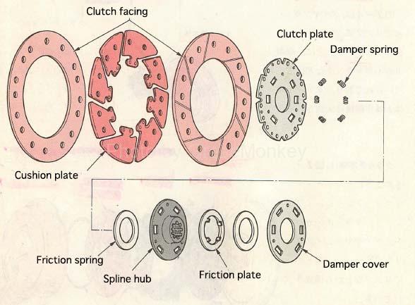
Figure 5: Clutch disc
The clutch disk is in uniform double-sided contact with the friction surfaces of the flywheel and the pressure plate, and plays a role of smoothly transmitting torque. As shown in Fig. 5, the clutch facing is riveted via a cushion plate attached to the steel clutch plate, and several coil springs are incorporated as damper springs on the circumference of the spline hub. .
This damper spring absorbs and mitigates the impact when torque is suddenly transmitted from the engine or drive wheels. (shock absorption during shifting)
Further, the clutch facing is required to have a coefficient of friction suitable for its application and to have a property that the coefficient of friction does not change much with changes in temperature.
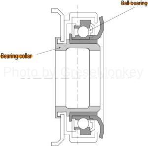
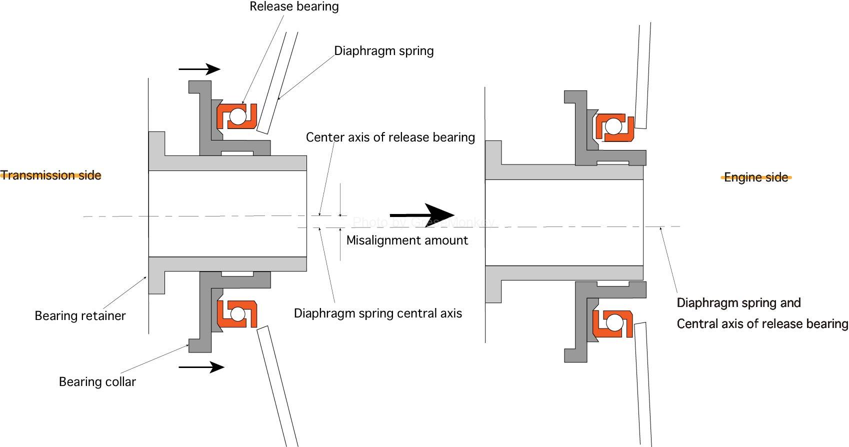
Figure 6: Release bearing and self-aligning function
The release bearing functions to transmit force from the clutch pedal to the clutch, which is a rotating body. In general, as shown in Fig. 6, oil-free angular ball bearings filled with heat-resistant grease are used, and the mainstream structure is press-fitted into the bearing collar.
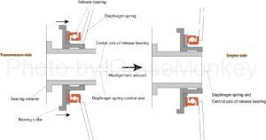
Figure 6-1: Release bearing and self-aligning function
In addition, the release bearing has the function of automatically compensating for minor misalignment of the center axes of the engine-side diaphragm spring and the transmission-side release bearing. When the release bearing itself moves, the misalignment is corrected.
Diaphragm spring clutch actuation
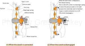
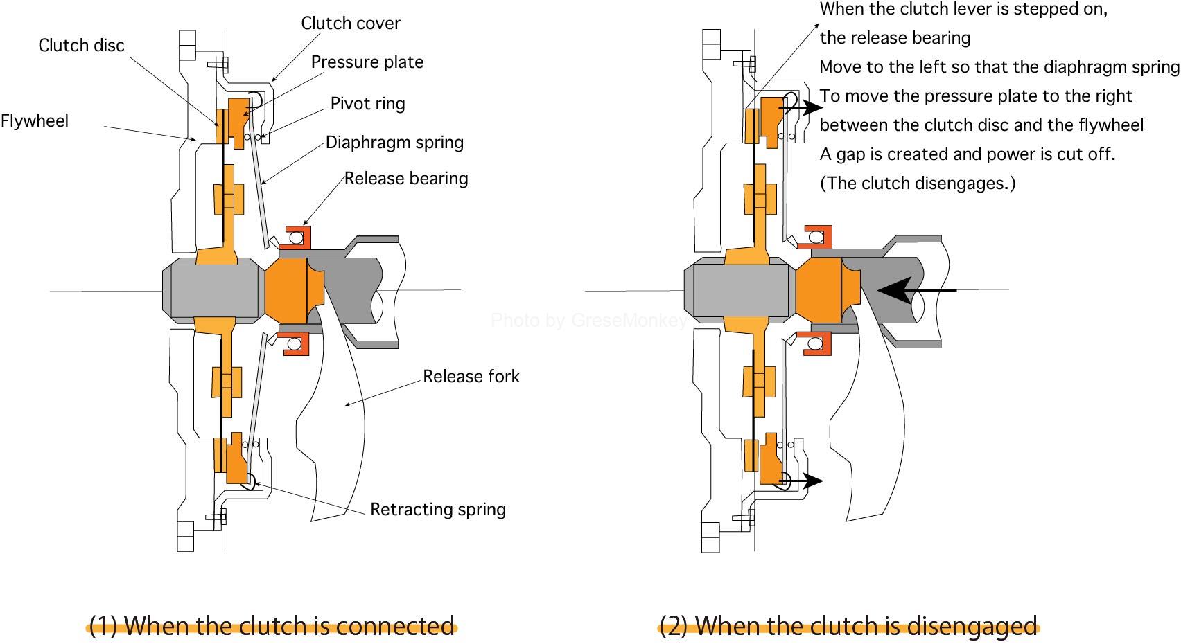
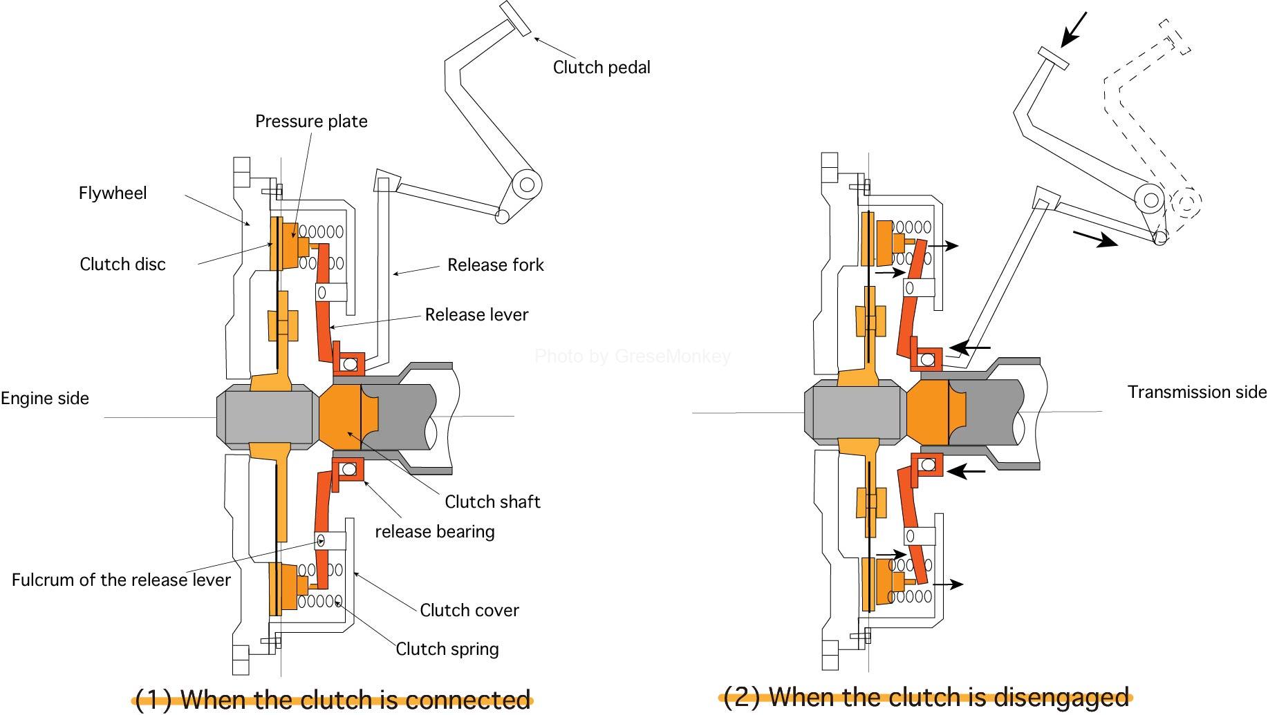
Figure 7: Function of diaphragm spring clutch
When the clutch is engaged, the spring force of the diaphragm spring pushes the clutch disc strongly against the flywheel via the pressure plate, rotating with the flywheel, constantly transferring power from the engine to the transmission. I’m telling you.
- When the clutch is disengaged
When the clutch pedal is depressed to cut off the power from the engine, the force generated by the movement of the release fork as shown in Fig. 7 (2) is transmitted to the release bearing and pushes the tip of the diaphragm spring. At this time, the pivot rings installed on both sides of the diaphragm spring act as a fulcrum, causing the outer circumference of the diaphragm spring to warp, and the pressure plate to move by the retracting spring, so the friction surface of the clutch disc (to the right in Fig. 7) A gap forms between the two, cutting off the power from the engine.
coil spring clutch
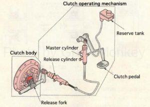
Figure 8: Coil spring clutch
Fig. 8 shows a coil spring type clutch, which is used in medium- and large-sized trucks and buses.
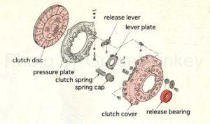
Figure 9: Clutch body components
Fig. 9 shows the main body of the coil spring type clutch. In principle, it is the same as a diaphragm spring type clutch, but instead of a diaphragm spring, multiple coil springs (clutch springs) are installed between the clutch cover and the pressure plate, and the clutch operation mechanism described later. It is a mechanism that connects and disconnects the clutch disc.
Also, the clutch disc is the same as the diaphragm spring system, splined to the clutch shaft and sandwiched between the flywheel and the pressure plate.
For reference, in the case of a large vehicle, if you order a clutch cover set for a large vehicle when replacing the clutch, the clutch cover and pressure plate are an assembly, but the clutch that is built in on the circumference In many cases, the clutch spring is compressed by passing a thick bolt through the spring and tightening it.
This is attached to the flywheel across the clutch disc, and the shaft is centered by loosening the spring fixing bolts on the circumference little by little.
- Working Principle of Coil Spring Clutch
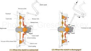
Figure 10: Operating principle of coil spring type clutch
From Fig. 10, when the clutch is engaged in (1), the clutch spring is strongly pressed against the flywheel via the pressure plate by the spring force of the clutch spring, rotates together with the flywheel, and transmits power from the engine to the transmission. there is
From Fig. 10, when the clutch is disengaged in (2), by stepping on the clutch pedal to cut off the power, the operation mechanism operates and the release bearing pushes the release lever, compressing the clutch spring. The pressure plate moves to the right in the figure, creating a clearance on the friction surface of the clutch disc, which cuts off the power.
Clutch operating mechanism
The clutch operation mechanism is a device that engages and disengages the clutch by operating a clutch pedal on the driver’s seat to move a release fork connected to the clutch body, and there are mechanical and hydraulic types.
mechanical operating mechanism
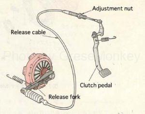
Figure 11: Mechanical operation mechanism
As shown in Fig. 11, this is a mechanical system in which the clutch pedal and release fork are directly connected with a cable.
By depressing the clutch pedal, the cable is pulled forward and the release fork also operates in sync. At this time, the diaphragm spring is actuated by moving the release bearing, creating a gap between the clutch disc and the flywheel, cutting off the power from the engine.
When the clutch pedal is released, the pedal return spring, release cable, release fork, and release bearing return to their original positions in that order. This activates the diaphragm spring, pushing the clutch disc against the flywheel and transmitting engine power to the transmission.
The advantage of this mechanical operation mechanism is that the force applied to the clutch pedal is transmitted directly to the release fork, so the structure is simple and maintenance and inspection are easy.
hydraulic operating mechanism
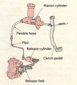
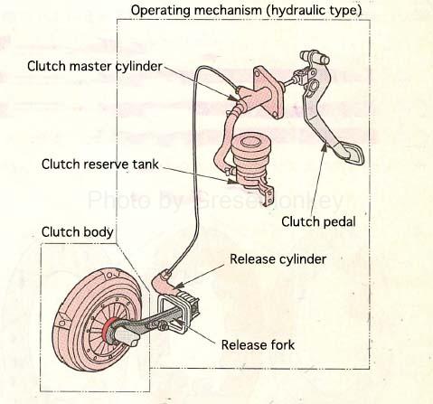
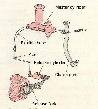
Figure 12: Hydraulic operation mechanism
As shown in Fig. 12, the clutch hydraulic operating mechanism converts the force applied to the clutch pedal into hydraulic pressure and transmits the hydraulic pressure to the release fork.
When the clutch pedal is depressed, hydraulic pressure is generated in the master cylinder and pushes the release fork through the push rod of the release cylinder.
This hydraulic operating mechanism ensures reliable clutch operation and light and smooth operation. While it is widely used in large vehicles that require a large pedaling force due to hydraulic pressure, it also exhibits an effective function in cases where frequent clutch operation is required, such as the clutch of a sports-type vehicle.
On the other hand, since the structure is complicated and hydraulic pressure is used, if air gets into the clutch fluid, the operation will be inaccurate, and there are points to be careful of, such as the amount and leakage of the clutch fluid.
The clutch fluid is often the same as the brake fluid.
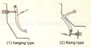
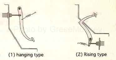
Figure 13: Clutch pedal
As shown in Fig. 13, there are two types of clutch pedals: hanging type and rising type.
A suspension type is adopted for a general passenger car. Some of the large trucks and buses with high vehicle height adopt the stand-up type.
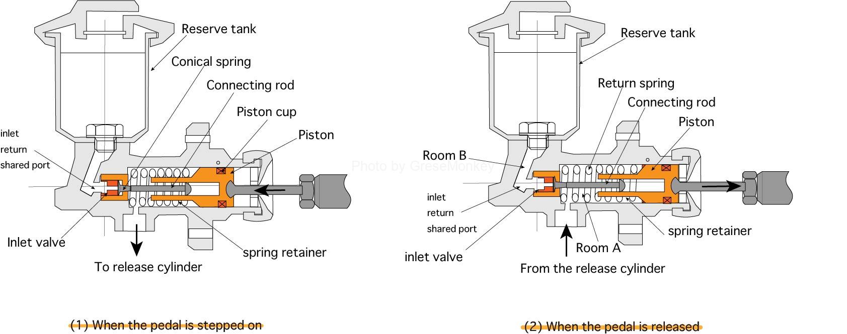
FIG. 14 shows a cross section of the master cylinder. The master cylinder can be roughly divided into two parts. They are the part of the cylinder where the piston slides due to hydraulic pressure and the part of the reserve tank for storing the clutch fluid.
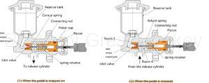
Figure 14: Master cylinder operation
The master cylinder generates hydraulic pressure for operating the clutch.
In FIG. 14(1), when the clutch pedal is slightly depressed, the piston is pushed and the clutch fluid in the cylinder is sent to the reserve tank. When the clutch pedal is further depressed and the piston moves, the spring retainer attached to the tip of the piston compresses the return spring to its maximum (the state where it can no longer be compressed).
At this time, since the connecting rod is free to move, the inlet valve moves to the left due to the spring force of the small conical spring installed at the tip of the rod, blocking the common inlet return port.
At the same time, the hydraulic pressure in the cylinder rises sharply, and the clutch fluid is sent to the release cylinder to move the release piston.
Figure 14: Master cylinder operation
In FIG. 14(2), when the clutch pedal is released, the piston is returned by the force of the return spring and the hydraulic pressure decreases, so the clutch fluid returns to the A chamber from the release cylinder side.
At the same time, the spring retainer pulls the connecting rod, and the inlet valve opens the common inlet return port.
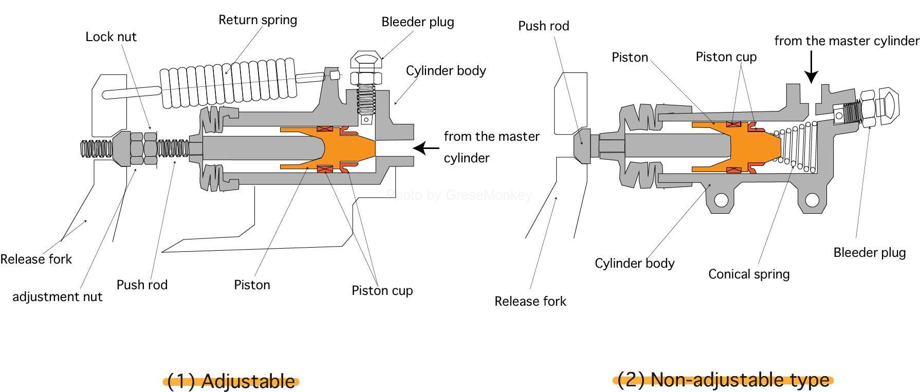
The release cylinder transmits the hydraulic pressure generated by the master cylinder to the clutch, and there are two types: an adjustable type with a mechanism that adjusts the clutch play (see note) and a non-adjustable type with an automatic adjustment mechanism.
In the release cylinder, hydraulic pressure from the master cylinder moves the piston and actuates the release fork via a pushrod.
FIG. 15 shows cross sections of adjustable and non-adjustable release cylinders.
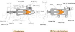
Figure 15: Release cylinder
- Figure 15 (1) Adjustment formula:The play of the clutch is done by changing the effective length of the push rod with the adjustment nut.
- Fig. 15 (2) Non-adjustable type:A conical spring built into the cylinder body keeps the push rod pressed against the release fork at all times, which keeps the release bearing in contact with the diaphragm spring, so the push rod moves as the clutch disc wears. automatically keeps clutch pedal play constant.
(Note) What is clutch play?
Play (travel) when the clutch pedal is depressed
- Free play (travel) of the clutch pedal until the tip of the master cylinder push rod pushes the piston
- Play (movement) until the piston of the master cylinder generates hydraulic pressure
- Play (movement amount) until the release bearing hits the diaphragm spring (or release lever) when hydraulic pressure is generated
There are these three, and these three play (movement amount) are generally called clutch play. This play (movement amount) can always be constant.
clutch booster
Clutch boosters reduce the operating force of the clutch pedal, and are used in vehicles such as large trucks and buses that use clutch springs with strong spring force.
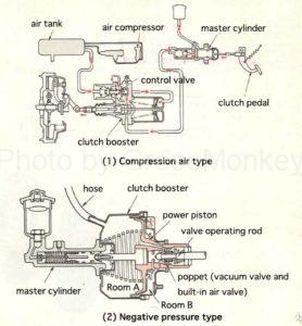
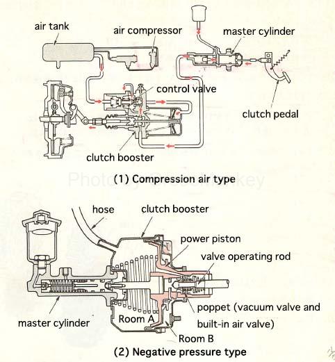
Figure 16: Clutch booster
Fig. 16 shows an example of a clutch booster. The compressed air type in Fig. (1) opens and closes a valve that controls the air inflow into the clutch booster using the hydraulic pressure of the master cylinder, allowing air to flow into the clutch booster. It is a method to operate a piston.
The negative pressure type shown in Figure (2) uses a valve operating rod to open and close the air valve and vacuum valve built into the poppet inside the clutch booster, thereby applying negative pressure to chamber A and atmospheric pressure to chamber B to move the power piston. This is the method to operate.
Citation sources, reference sites, etc.
Some of the text on this site has been quoted from the following books, publications, and websites.
- Well-understood 3rd class car mechanic chassis Written by Noboru Oho Kobunsha
- “Class 3 car chassis supervised by the Automobile Transportation Bureau, Ministry of Land, Infrastructure, Transport and Tourism” Japan Federation of Automobile Maintenance Associations