Force on suspension and body
Inertia spindle
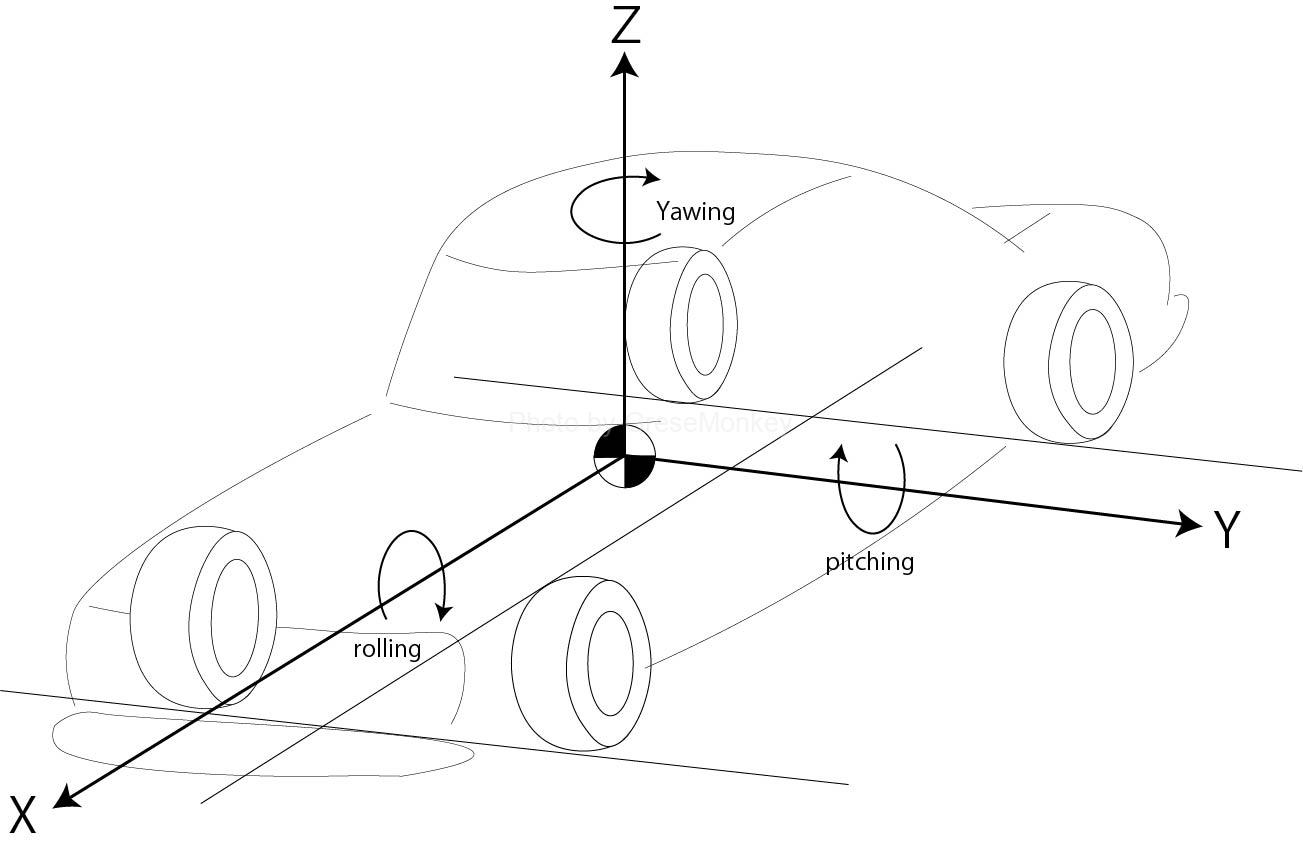
The behavior of the car controlled by the suspension can be divided into three movements, rolling, pitching, and yawing, on the X-axis, Y-axis, and Z-axis shown in the above figure. Of these movements, consider the movement when the car is viewed from the side, that is, the pitching, which is the movement back and forth around the Y axis.
table of contents
- The force caused by the suspension arm
- Anti-squat power
- Force acting on the car body when accelerating
- For semi-trailing arm type
The force caused by the suspension arm
In an FR type car, when you put it in the D range or step on the accelerator to accelerate, I think that you have experienced that the rear part of the car body has dropped sharply, but two forces act on this. are doing.
One is the inertial force that tries to prevent acceleration. When a car tries to accelerate, the force that tries to keep the running state (low speed or deceleration) just before accelerating works, and the force that works on the car body to keep the state just before accelerating. It is called inertial force.
As the car accelerates, this force acts in the direction of returning it to its original state when the force acting on the vehicle body tries to change. In other words, if you try to accelerate, on the contrary, it acts as if you do not accelerate.
The second is the driving force applied to the wheels. As the name implies, this increases in proportion to the acceleration of the car.
These two forces generate a downward force on the vehicle body during acceleration. And it is ** anti-squat ** that tries to suppress this downward movement.
Anti-squat power
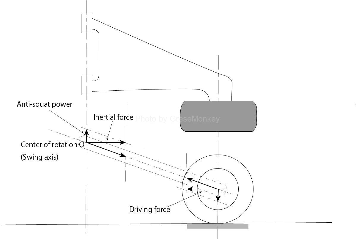
Figure 1: Force generated by driving force
In the case of a full trailing arm suspension, the tire can rotate freely with respect to the suspension arm during acceleration, so the driving force acts on the center of the wheel. (refer graph1)
At this time, the swing axis (rotation axis) of the suspension arm becomes the rotation center when the tire (center) rotates. Then, the driving force generates a force for pushing up the swing shaft (rotation center O) of the suspension arm.
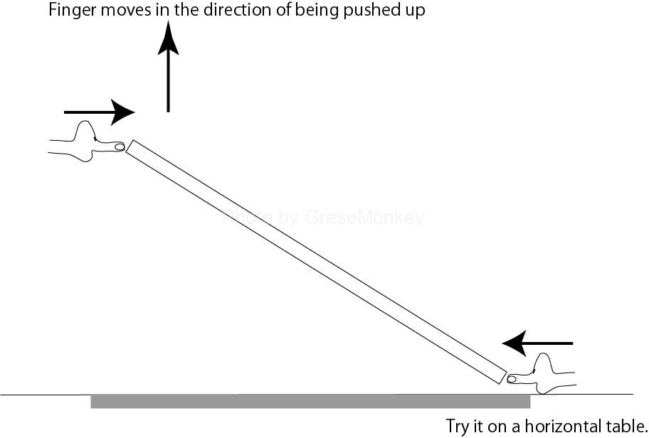
Figure 2: Principle of anti-squat force
For example, as shown in Fig. 2, when the vertical movement is fixed on the table and one side of the rod is pushed, the other side is lifted by the same principle.
The force that pushes up the car body acts in the opposite direction to the force that pushes down the rear part of the car body during acceleration. In other words, it works as an anti-squat force that tries to suppress the movement of the hips.
This anti-squat force should normally act on the center of rotation O (swing axis: mounting point of the vehicle body), but since the length of the suspension arm is shorter than the entire vehicle body, it is considered to act on the center of the tire. But there is no big difference.
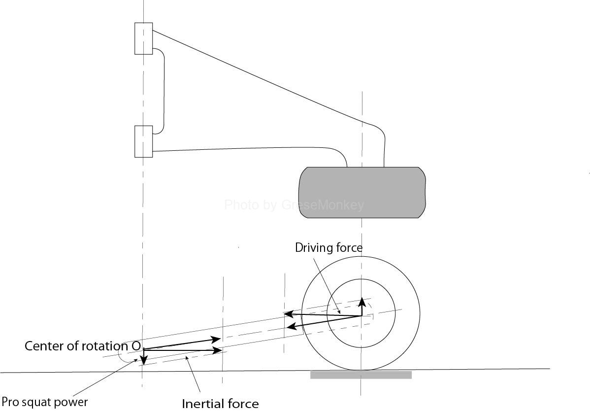
Figure 3: When the center of rotation is low
As shown in FIG. 3, when the center of rotation O is lower than the center of the wheel, the driving force generates a force to push down the vehicle body. In this case, it works to encourage squats (force to lower the hips), so it is sometimes called progress squats or pro squats.
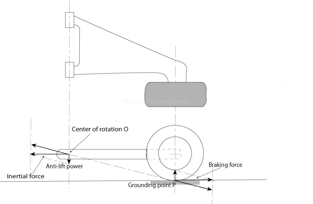
Figure 4: Force generated by braking force
Consider the case when the brake is applied as shown in Fig. 4. When the brake is applied, the caliper fixed to the suspension arm tries to stop the rotation of the tire, and the tire cannot rotate freely, so that the braking force acts on the ground contact point of the tire. At this time, the braking force acts to push down the rotation center O (swing shaft). In other words, this force acts as an anti-lift force.
Force acting on the car body when accelerating
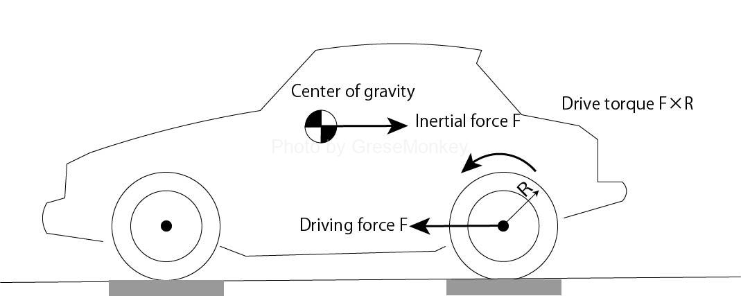
Figure 5: Force generated at the rear of the vehicle during acceleration
The force to lower the buttocks of the car body due to the phenomenon of lowering the hips during acceleration is considered as follows. (See Figure 5)

Figure 6: Squat force due to drive torque
The driving force F acts on the ground contact point of the tire, and this force can be considered separately as the forward force F acting on the center of the tire and the driving torque F × R. Here, R refers to the radius of the tire.
As mentioned earlier, in the case of a full trading arm suspension, the tire can rotate freely with respect to the suspension arm, so this drive torque F × R is transmitted to the suspension on the rotation axis of the tire. It will be transmitted to the vehicle body via the differential gear.
At this time, the front wheel side is lifted by the force of (F × R) / L obtained by dividing this drive torque by the wheelbase L, and the rear wheel side is pushed down. (See Figure 6)
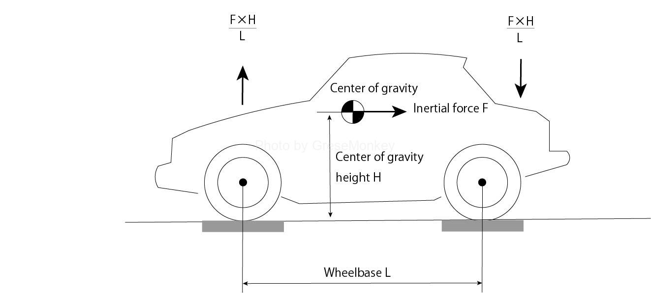
Figure 7: Squat force due to inertial force
The inertial force generated by acceleration is equal to the driving force, but it acts on the center of gravity of the vehicle, so if the height of the center of gravity is H, the front wheel side is lifted by the force of (F × H) / L, and the rear is lifted. Try to push down on the wheel side. (See Figure 7)
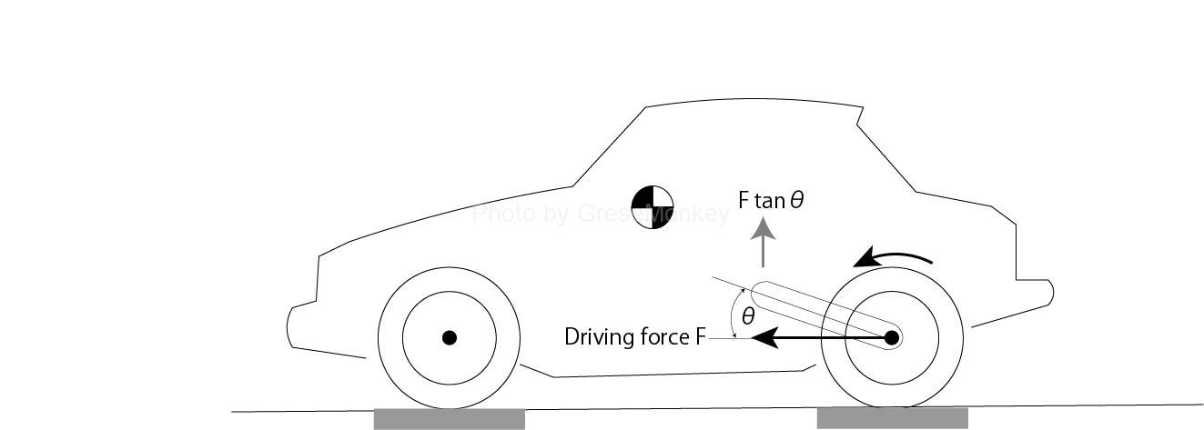
Figure 8: Anti-squat force
On the other hand, the forward force (driving force) acting on the center of the wheel tends to push down depending on the inclination of the suspension arm, but basically pushes down the rear part of the vehicle body. The force at that time is F × tan θ, which is the anti-squat force. (See Figure 8)
Therefore, the squat force that pushes up the front wheel side and pushes down the rear wheel side can be expressed by the sum of the two forces.
$$ \frac{F × R}{L} + \frac{F × H}{L} $$
Will be. Therefore, in order to reduce the squat during acceleration to zero, the squat force and anti-squat force should be equalized.
$$ \frac{F × R}{L} + \frac{F × H}{L} = F × \tan\theta $$
$$ ∴ \frac{R + H}{L} = F × \tan\theta $$
It means that the mounting position of the suspension arm should be decided so as to be (see Fig. 9).
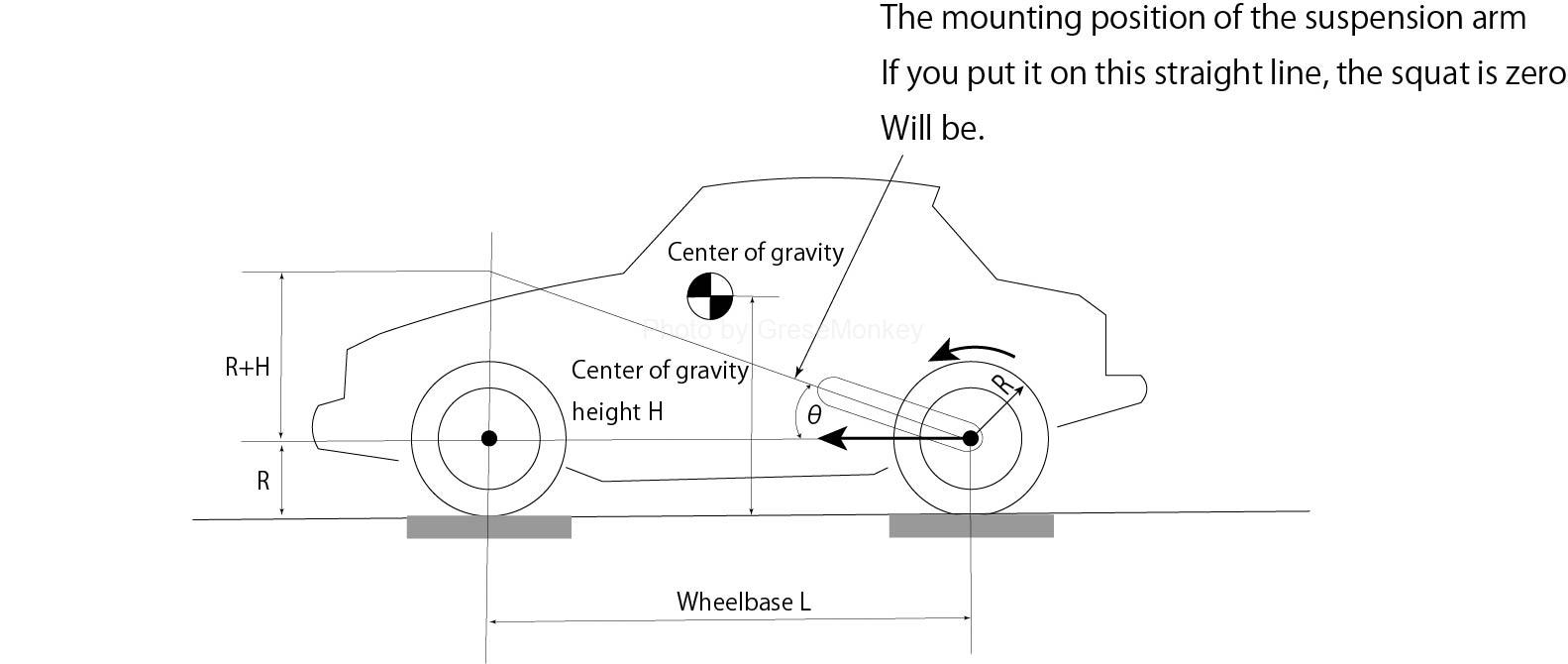
Figure 9: Squat Zero Suspension Geometry
That is, as shown in FIG. 9, it suffices if it is on a straight line connecting the center of the front wheels with the radius of the tire and the height of the center of gravity and the center of the rear wheels.
For semi-trailing arm type
In order to obtain the center of rotation O in the case of the semi-trailing arm type, first, in the top view (plan view) of the semi-trailing arm, the mounting point (swing axis) on the vehicle body side of the suspension arm is linear. The point where it is tied and extended and intersects with the extension of the tire center line is the rotation center O on the plan view. (See Figure 10)
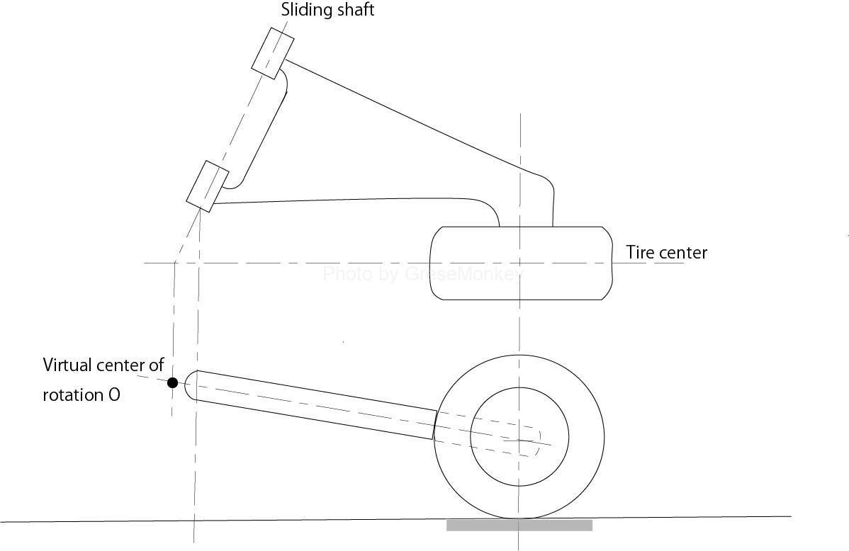
Figure 10: Semi-trailing arm type rotation center
A point where a perpendicular line is drawn from the center of rotation O on this plan view and intersects with a straight line extending the suspension arm in the side view (side view) of the tire. This is the center of rotation O in the case of the semi-trailing arm type.
That is, in the case of the semi-trailing arm type, the center of rotation is a virtual center of rotation in which the swing axis does not actually exist. (The center of the entity does not exist in the car body) This is the same idea as the momentary center when the roll center is sought.
After finding the center of rotation O, it is exactly the same as in the case of the trailing arm type, and the anti-squat and anti-lift are determined by the positional relationship between the center of rotation O and the force acting on the tire.
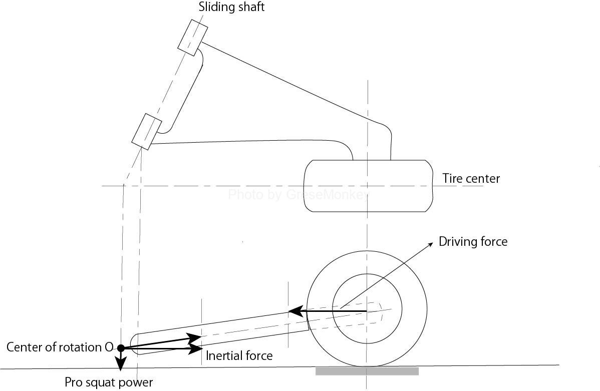
Figure 11: Example of a real semi-trading arm type
The semi-trailing arm type camber change is a negative camber when the tire bounces (bumps) up from a position (horizontal state) at the same height as the swing axis, and a positive camber when it rebounds down.
In addition, the toe change tends to be toe-in in both the bound stroke and the rebound stroke. Therefore, there are many cases where the swing axis is set below the center of the axle so that a large area of negative camber can be used.
This will promote the squat state during acceleration, but it is difficult to give anti-squat characteristics with the semi-trailing arm type. For example, in an FR type car, if you try to set the position of the swing axis high, it will be obstructed by the rear seats and floor, and the degree of freedom of setting will be difficult. In the FR type car using the semi-trailing arm type, the tail-down phenomenon occurs at the time of acceleration because it is a structure that is difficult to give anti-squat characteristics. Future improvements are expected by reviewing changes and improvements in the suspension system and the degree of freedom in design.
Citation sources / references / websites
Some of the texts on this site are quoted from the following books, publications, and websites.
・ “Vehicle motion performance and chassis mechanism” by Takaaki Uno Grand Prix Publishing
・ “Suspension mechanism and running performance” by Manabu Kumano Grand Prix Publishing