Alignment measurement gauge
Table of Contents
Turning Radius Gauge
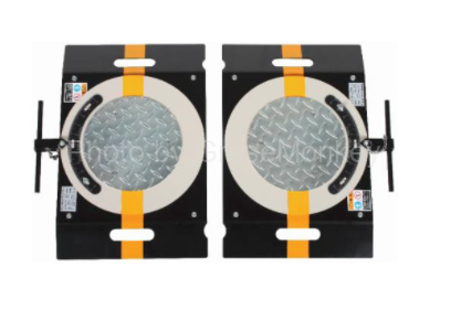
Figure 1: Appearance of Turning Radius Gauge
The turning radius gauge has a table-like appearance as shown in Fig. 1, and is a device that measures the steering angle of the front wheel. It is also used in combination with the front wheel alignment tester when measuring casters and kingpin angles (tilts) in wheel alignment.
When measuring the turning angle of the front wheel, place the left and right wheels on the turning radius gauge and steer the steering wheel so that the turntable rotates with the wheel and the steering angle of the wheel can be measured by the pointer and scale. It has become.
There are two types of turning radius gauges, fixed type and mobile type, but generally, two types for one mobile type are used for measurement.
Turning radius gauge structure and mounting method
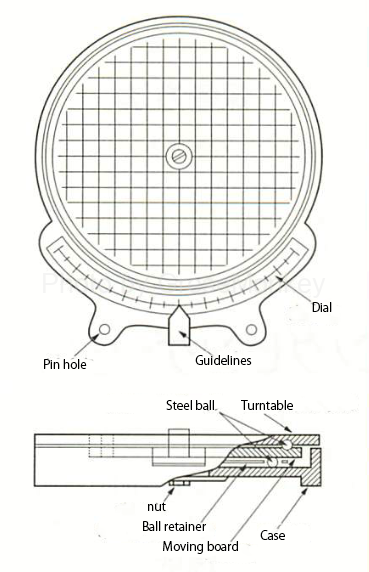
Figure 2: Structure of the turning radius gauge
The turning radius gauge is divided into a turntable, a moving board, and a case as shown in Fig. 2. The pointer is attached to the moving board and the dial is attached to the turntable. The turntable and the case are provided with pin holes so that they can be fixed by inserting the pins.
A large number of steel balls are incorporated between the turntable and the moving board so that the turntable can rotate smoothly even under load. Several steel balls are also placed between the moving board and the case at appropriate intervals by retainers so that the moving board can move within the holes provided in the lower surface of the case.
The moving board is supported inside the case by four coil springs, and the moving board is always kept in the center position when there is no load. In addition, the turntable, the moving board, and the case are connected by the central bolt in a state where an appropriate clearance (gap) is given.
How to measure turning radius gauge
To measure the turning angle with the maximum steering angle, follow the procedure below.
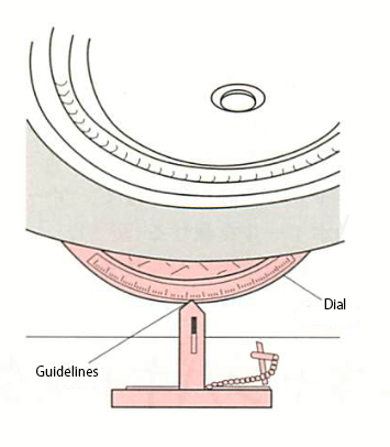
Figure 3: Turning Radius Gauge Setup
- Place the gauge on a flat surface with the tread surface of the front wheel.
- Jack up to raise the front wheels.
- Attach a pin to fix the turntable and the case, and position the gauge so that the front wheel is in a straight line and the center line of the gauge is aligned with the center line of the tire.
- Gently lower the jack and place the front wheel on the gauge. (Fig. 3)
- Remove the left and right fixing pins and adjust the zero point of the scale.
- Steer the steering wheel all the way to the left or right and read the scale at that time.
How to store the turning radius gauge
- Be sure to insert the fixing pin when moving or storing.
- Avoid getting dust and water.
- Do not put it on the turning radius gauge by riding on the vehicle.
Camber Caster King Pin Gauge
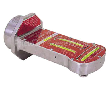
Figure 4: External appearance of camber caster kingpin gauge
Wheels are required to have performance such as straightness for stable running, turning performance, and restoring force for returning to a straight running state. To achieve this, the vehicle needs proper wheel alignment (four-wheel alignment).
- Five elements of wheel alignment
- Camber
- Casters
- Kingpin angle (Kingpin tilt angle)
- Toin
- Left and right cutting angle
Of these five elements, the camber, casters and kingpin angles can be measured with a camber caster kingpin gauge. There are various types of this gauge, but the type that is attached using a magnet is generally used. (Fig. 4)
Structure and mounting method of camber, caster and kingpin gauge
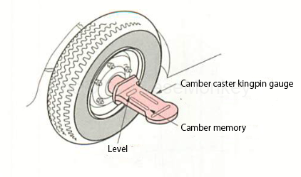
Figure 5-1: Structure and setup method of camber, caster, and kingpin gauge
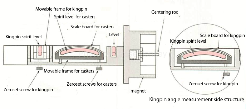
Figure 5-2: Structure and setup method of camber, caster, and kingpin gauge
As shown in Fig. 5-1 and Fig. 5-2, the camber caster kingpin gauge consists of a magnet for fixing with a gauge, a camber and a spirit level for measuring the caster and kingpin angle.
This gauge is attached to the hub of the front wheel using a magnet, and if the air of the level in the center of the gauge is set to the center position, the rotating surface of the wheel and the dial of the gauge will automatically be at right angles. It is built in.
If it cannot be directly attached to the hub, attach an auxiliary attachment adapter called a compensator to the rim of the wheel as shown in Fig. 6, and fix the gauge to this for measurement.
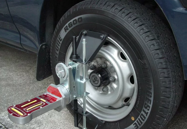
Figure 6: Compensator
How to measure camber
In the camber measurement, before making the measurement, check the kingpin, ball joint, wheel bearing, etc. for any abnormality, and correct any abnormality. Also, as the place to measure in order to measure the accurate measured value, select a flat paved place, set the tire pressure to the specified value, and leave the car empty. In addition, the vehicle body is shaken up and down to stabilize the suspension spring. (In the case of independent suspension)
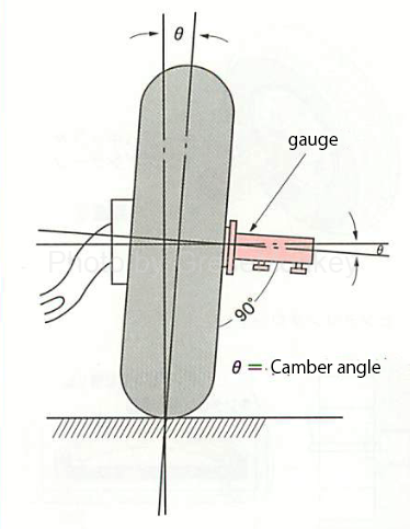
Figure 7: Camber measurement
When you are ready, follow the steps below to measure the camber.
- Put the front wheel straight ahead
- Remove the hub cap and install the gauge. (In some cases, use a compensator)
- Align the tip of the centering rod of the gauge with the center of the hub of the vehicle (center of the spindle), and install it with the center correctly centered.
- Level the camber caster kingpin gauge so that the air bubbles in the level of the camber caster kingpin gauge body become “0”.
- Read the camber scale at the center of the bubble in the camber scale. (Fig. 7)
- Measure the front wheel on the opposite side in the same way.
How to measure casters
The casters and kingpin angle cannot be measured accurately when the wheel turns, so be sure to apply the foot brake. Since the vehicle needs to be empty at the time of measurement, a pedal stopper as shown in FIG. 8 may be attached.
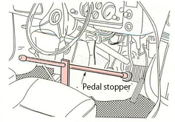
Figure 8: Pedal stopper
The procedure for measuring the caster and kingpin angle is the same, and the procedure is as follows.
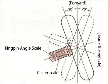
Figure 9: Reading caster measurements
- Place the wheel to be measured on the turning radius gauge. After that, install the camber caster kingpin gauge in the same way as the camber measurement.
- Gently turn the front wheel 20 ° to the outside of the center of the vehicle.
- Adjust the air bubbles in the caster scale to “0” with the adjuster screw.
- Gently turn the front wheel 20 ° toward the center of the vehicle from the straight-ahead state.
- Read the caster scale at the center of the bubble in the caster scale. (Fig. 9)
- Measure the front wheel on the opposite side in the same way.
- For the kingpin angle, perform the same procedure as 1 to 6 above with the kingpin angle scale on the gauge, and read the measured value. (Kingpin Angle Scale)