Wheel alignment
The wheels of the car are provided with angles to allow the car to perform appropriate movements for each of these purposes in order to maintain driving performance such as straightness, turning, and restoring force to the straight state. This alignment between the wheels is called wheel alignment.
Typical elements of wheel alignment include the positional relationship between the front and rear wheels of an automobile, camber, casters, kingpin tilt angle (SAI), toe-in, and the center position of the steering wheel.
The basis of wheel alignment is that each element of the left-right alignment of the front and rear wheels of the automobile works correctly and is set symmetrically.
Nowadays, high-speed driving on highways is becoming more common, and it is important to correctly maintain not only the front wheel alignment but also the rear wheel alignment, which has a great effect on straight-line performance. Alignment as a whole is called total wheel alignment (all-wheel alignment).
Table of Contents
Wheel alignment structure and function
Positional relationship between front and rear wheels
If the distance between the front, rear, left, and right wheels shown in FIG. 1 is incorrect in an automobile, the steering wheel will be taken off and the tires will be unevenly worn, which will adversely affect turning and straight running performance. The mutual position of the front, rear, left and right wheels can be confirmed by the distance between the wheelbase and the tread specified for the vehicle.
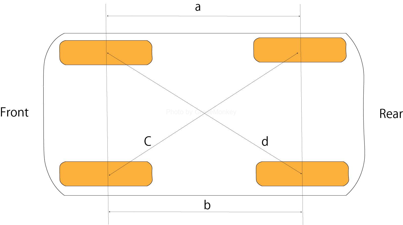
Figure 1: Positions of the relationship between the front and rear wheels
Left-right difference in wheelbase
The displacement between the front, rear, left, and right wheels occurs when the axle mounting position shifts in the front-rear direction with respect to the traveling direction as shown in Fig. 2. The angle that deviates in the front-rear direction with respect to this traveling direction is called the setback angle, and this setback angle is used for measurement in four-wheel wheel alignment testers and the like.
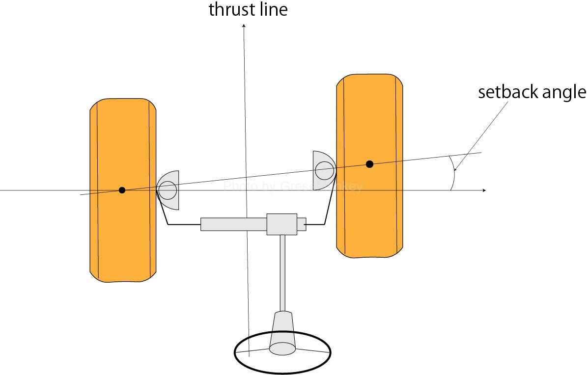
Figure 2: Setback angle
Fig. 3 shows the state of the laterality of the wheelbase, and it is a good idea to measure the distance between the front, rear, left and right wheels and compare it with the specifications of the wheelbase, and it is possible to confirm the presence or absence of the setback angle. ..
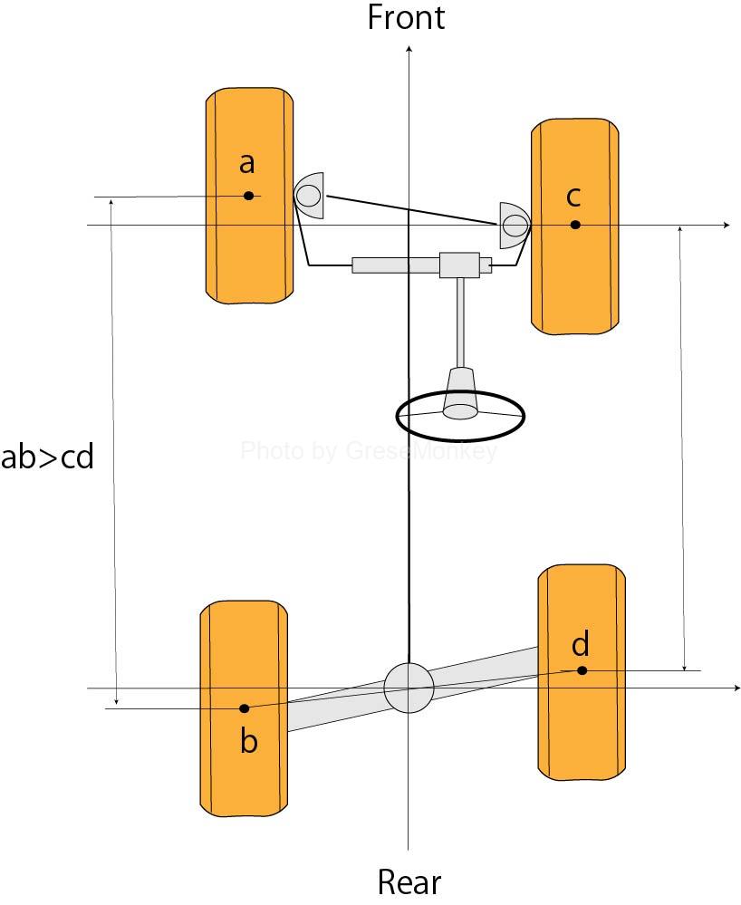
Figure 3: Left-right difference in foil base
Left-right difference of tread
The deviation between the front, rear, left and right wheels can be confirmed by measuring the distance between the front and rear treads as shown in Fig. 4 and comparing them with the tread specifications.
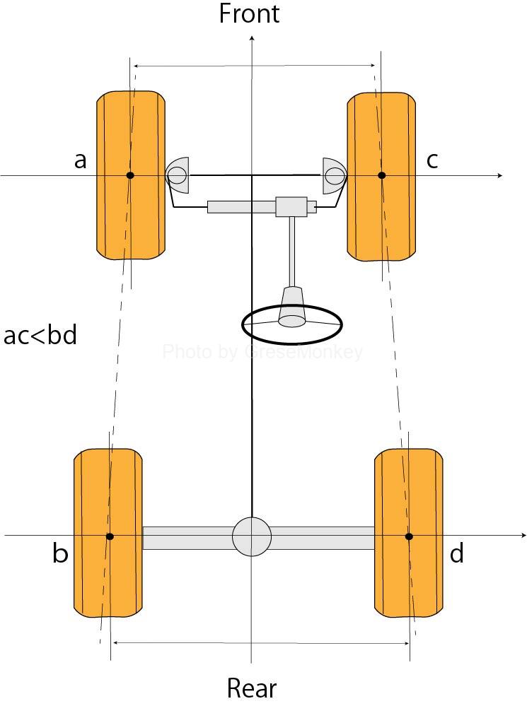
Figure 4: Front and rear difference of tread
Camber
As shown in Fig. 5, the angle between the center surface of the wheel and the vertical line with respect to the road surface is called the camber, and the wheel is slightly open upwards or downwards. That is. These cambers are set to a range of about 1 ° for each of plus and minus on the front side, and a range of about 1.5 ° for each of plus and minus on the rear side of the independent suspension type suspension.
In the past, the main purpose of providing camber was to reduce steering operation, prevent tires from coming off and prevent downward opening, etc., but nowadays, the performance of suspensions, bearings, ball joints, tires, etc. is improved. The role of the camber changes greatly depending on the power steering, etc. In particular, in the case of the independent suspension type suspension, the tires and the road surface are grounded as upright as possible in order to respond to changes in the load of the car, roll motion during turning, and unevenness of the road surface. Therefore, it has been devised to maintain the maximum grip of the tire.
Change in camber when turning
As shown in Fig. 5, the camber of the wheel with respect to the road surface when the vehicle body tilts during turning varies greatly depending on the suspension model. With the axle suspension, the camber changes little, but with the independent suspension, it changes significantly.
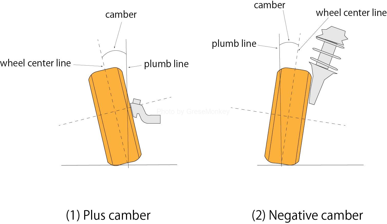
Figure 5: Camber
Further, when the wheel has a plastic camber, the ground contact surface of the tire is deformed as shown in FIG. 6, and a lateral force is generated in which the tire tries to roll inside the inclination. This is called canvas last, and it increases as the camber angle increases.
If the left and right cambers are equal, the left and right canvas lasts will be equal when going straight and the force will be offset, but when turning, in the case of an independent suspension, the outer wheel camber is generally large and the inner wheel camber is small. Therefore, the outer wheel has a larger canvas last than the inner wheel.
In this case, the direction of the force of the canvas last of the outer wheel is opposite to the cornering force, so that the force acts in the direction of reducing the cornering force. Therefore, in order to prevent this, in passenger cars, as shown in Fig. 6, the camber when going straight is set to minus, and the camber of the outer wheel when turning is made as small as possible to increase the cornering force and improve turning performance. Some are improving. However, if the minus camber is also made larger than necessary, the straight running stability will be impaired.
Some plastic camber vehicles are also equipped with a camber control mechanism that suppresses the camber change of turning as much as possible by utilizing the arrangement of suspension links and the deformation of the bush used for the suspension links.
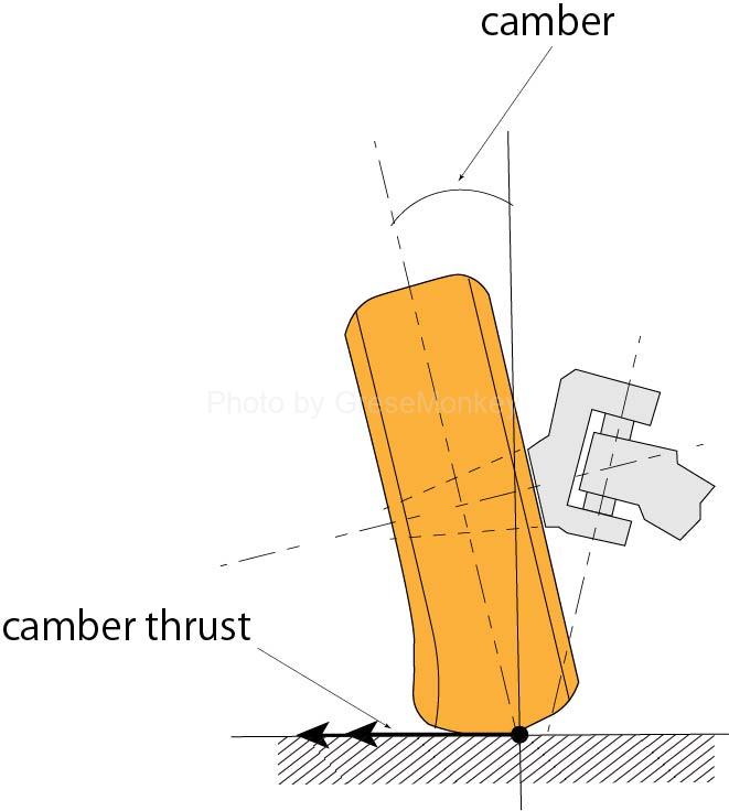
Figure 6: Canvas last
Casters
When the front wheel is viewed from the side, the kingpin is slightly tilted forward or backward with respect to the vertical line, as shown in Fig. 9. This inclination is called a caster and is represented by the angle between the kingpin center line and the vertical line.
A kingpin whose top is inclined backward with respect to the direction of travel is called a plus caster, and one in the opposite direction is called a minus caster, but in general, there are many plus casters.
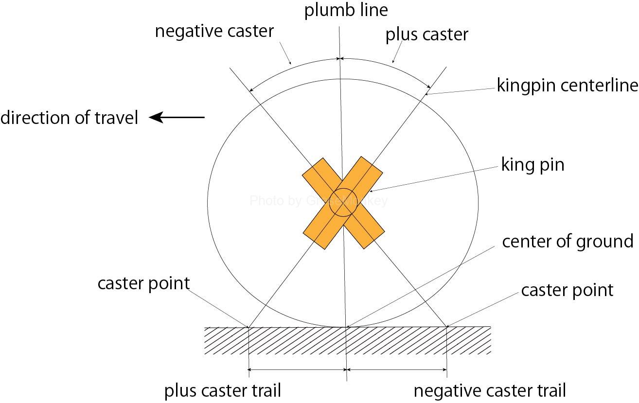
Figure 9: Caster
Further, from FIG. 9, the point where the extension line of the kingpin center line intersects the road surface is called a caster point, and the distance in the front-rear direction from the center of the tire contact patch is called a caster trail.
Caster effect
- Straight ahead
The tire contact patch center of the wheel is located at a position deviated from the original center position due to the inclination to the contact patch due to the influence of the camber, casters, kingpin tilt angle, and the like.

Figure 10: Casters when going straight
Fig. 10 shows the ground contact surface of the wheel as seen from directly above. ‘) Is represented, and a and a’are in front of the tire contact patch O and O’by the plus trail (same on the left and right), and inside by the offset (same on the left and right).
At this time, the driving force (P), (P’) acts in the directions of a and a’, and the rolling resistance (F) and (F’) of the tire acts on O and O’in the direction opposite to the driving force. To do.
Therefore, a counterclockwise moment (T) centered on a is generated on the left wheel, and a clockwise moment (T’) centered on a’is also generated on the right side.
Therefore, if a moment is generated in the wheel, the wheel rolls in the direction of the larger moment, but in this case, the moments T and T’generated around a and a’have the same magnitude and opposite directions, so they cancel each other out. Keep the wheel straight.
Note that a-O and a’-O’are called wheel lever arms, and in reality, this action generates a moment around the kingpin axis.
- When turning
When the steering wheel is rotated to the left, as shown in FIG. 11, the tire contact centers O and O’move around a and a’with the wheel lever arm as the radius, and the tire contact center moves according to this offset amount.
Therefore, the center of contact with the tire changes so that the right wheel is large and the left wheel is small.
This movement of the tire contact patch, that is, the inclination of the tire contact patch, tries to return to the original state due to the weight of the vehicle itself, and as a result, the moment T’acting on the right wheel increases, so that the wheel tries to return straight. Restoring force is generated in the direction. This action is called the caster effect.
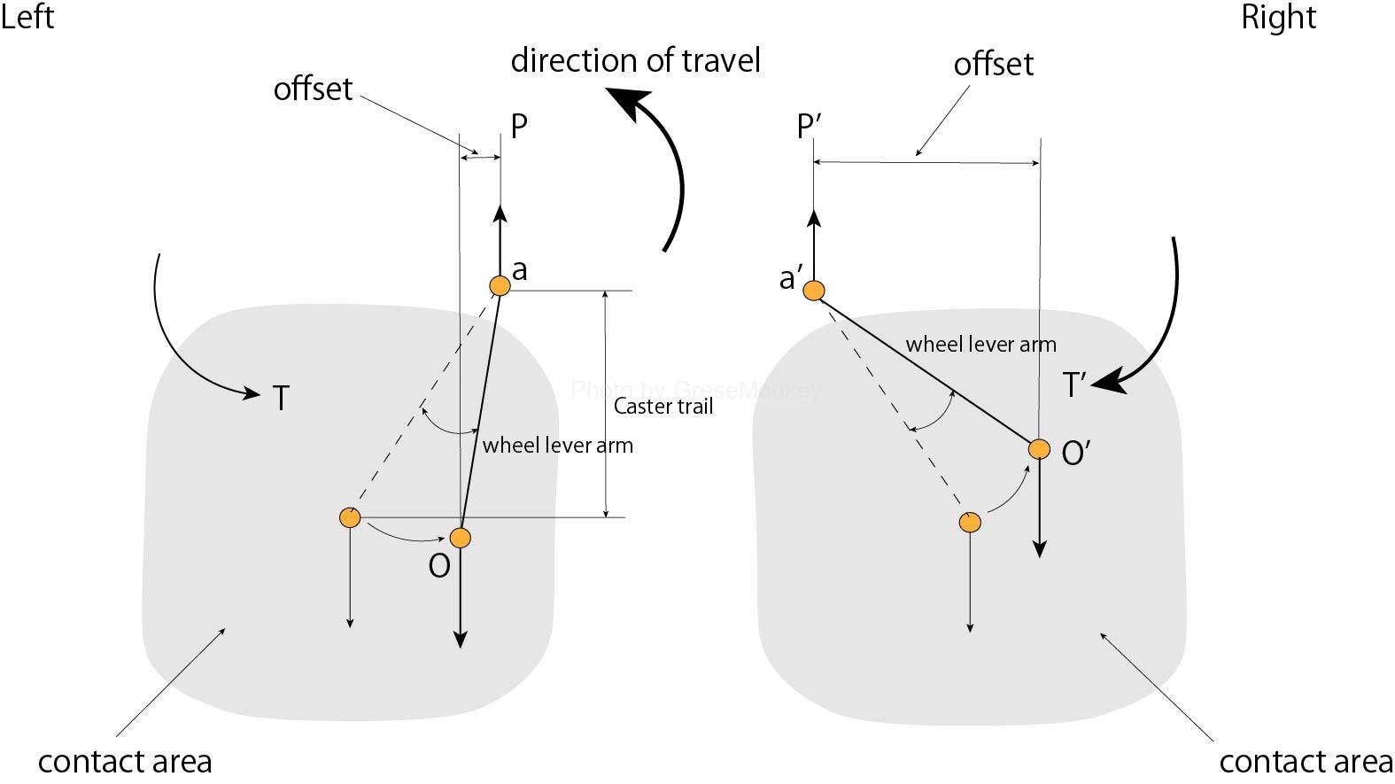
Figure 11: Caster when turning
Further, the caster trail of FIG. 10 has a straight-ahead restoring force and an action of suppressing a force that makes the wheel unstable by pulling a force applied to the wheel from the traveling direction. However, in order to lengthen the caster trail, the caster angle must be increased and the wheel lever arm must be lengthened, which increases the offset amount during turning and increases the restoring force, but the operating force required for steering wheel operation. If the number of wheels increases or the sense of unity during driving is lost, the steering feeling will deteriorate.
Therefore, the straightness is shared not only with the casters but also with the tires and suspension, and at the same time, even if the caster angle is constant as shown in Fig. 12, the caster trail can be freely moved by moving the kingpin axis back and forth from the center of the axle. Depending on the setting method, the casters are made smaller to improve the steering feeling. And so on.

Figure 12: How to set the caster trail
Kingpin tilt angle (SAI)
The kingpin is installed at an inward tilt as shown in Fig. 13, and the angle between the center line and the vertical line is called the kingpin inclination angle (SAI), and the distance between the road surface intersection of the kingpin axis centerline and the center of the tire tread is the kingpin. It is called an offset.

Figure 13: Kingpin offset
Further, as shown in FIG. 13, the horizontal distance between the kingpin shaft and the tire center is called a spindle offset, and the larger the value of these offsets, the larger the moment around the kingpin.
Change in offset amount
Considering the case where there is no kingpin tilt angle, the offset amount (A) becomes large as shown in Fig. 14, and the load of the vehicle body acts as a force to directly bend the kingpin.

Figure 14: When the kingpin has no tilt angle
Further, since the running resistance acts on the center of the ground contact surface of the tire, a force acts on the wheel to rotate the wheel in the direction of the arrow in FIG. 14 around the kingpin during running and braking. This force acts to swing the wheel back and forth during running and braking, and the force from the road surface is directly transmitted to the link mechanism of the steering device, resulting in a problem in steering operation.
In order to reduce these problems, the kingpin is tilted to reduce the offset amount, and the spindle offset is reduced as shown in Fig. 15 to reduce the generated moment, and the wheel runout and handle are moved to one side. The phenomenon taken is reduced.
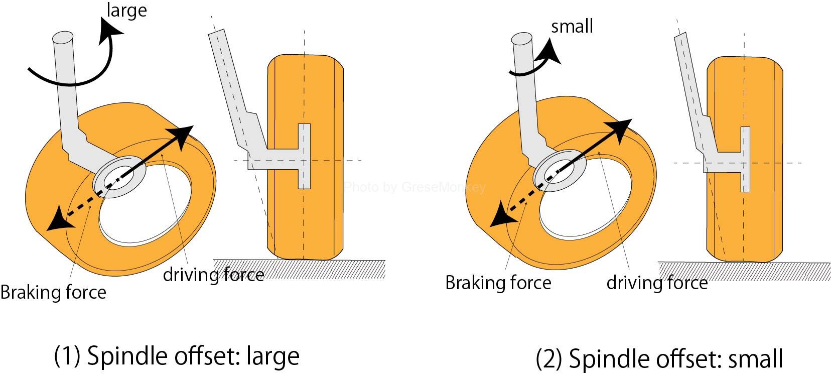
Figure 15: Spindle offset
Toe-in
Regarding the difference in distance between the front side and the rear side of the wheel when the car is viewed from above, when the front side is smaller than the rear side as shown in Fig. 16, it is called toe-in, and when it is larger, it is called toe-in. Generally, toe-in is adopted. ing.
Traditionally, toe-ins have been used primarily to prevent the front of the wheel from trying to widen outwards due to the plastic camber, but with the minus camber, the performance of suspensions, bearings, ball joints, tires, etc. has improved. The main purpose is to ensure straight-line stability.
Toe-in and side slip
When the toe-in is provided, an inward thrust force is generated on the tire as shown in FIG. In addition, even those that use a minus camber generate inward thrust force, which becomes a combined thrust force and appears as a side slip, so it is not possible to provide a very large toe-in on the front wheels.
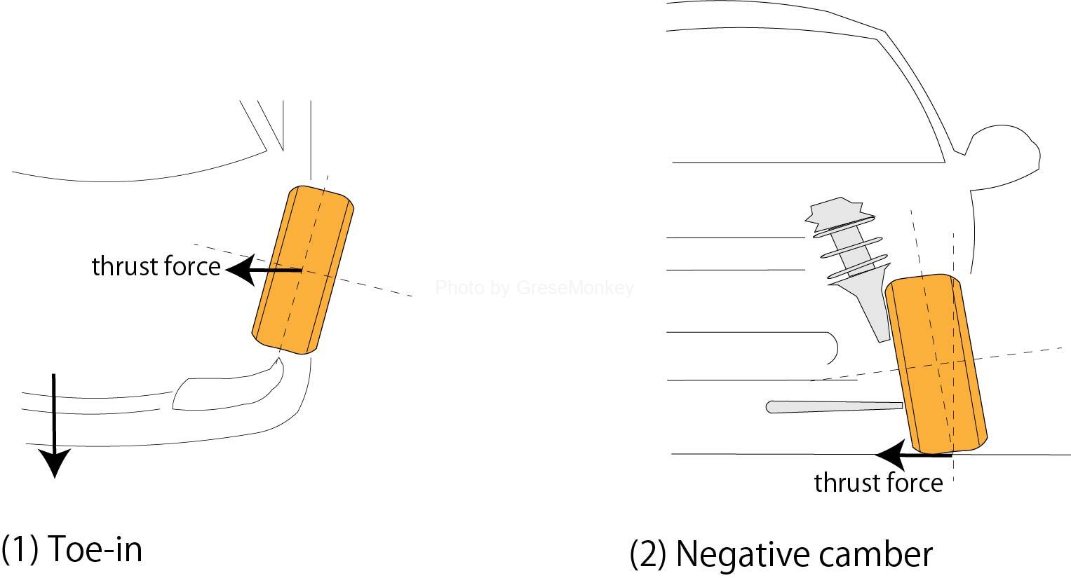
Figure 17: Side slip
Toe and Kingpin tilt angle
While driving, the center of the axle moves up and down in an arc depending on the top and bottom of the tire. At this time, the tie rod also moves in the same way, but the tie rod is key.
Due to the influence of the angle of inclination of the ngpin, the toe changes by moving differently from the center of the axle.
- Toe change when going straight
When the tire moves up and down, the amount of movement of the tie rod is almost equal to the amount of movement of the center of the axle in the inward and outward directions as shown in FIG. 18, so the change in toe is not so large.
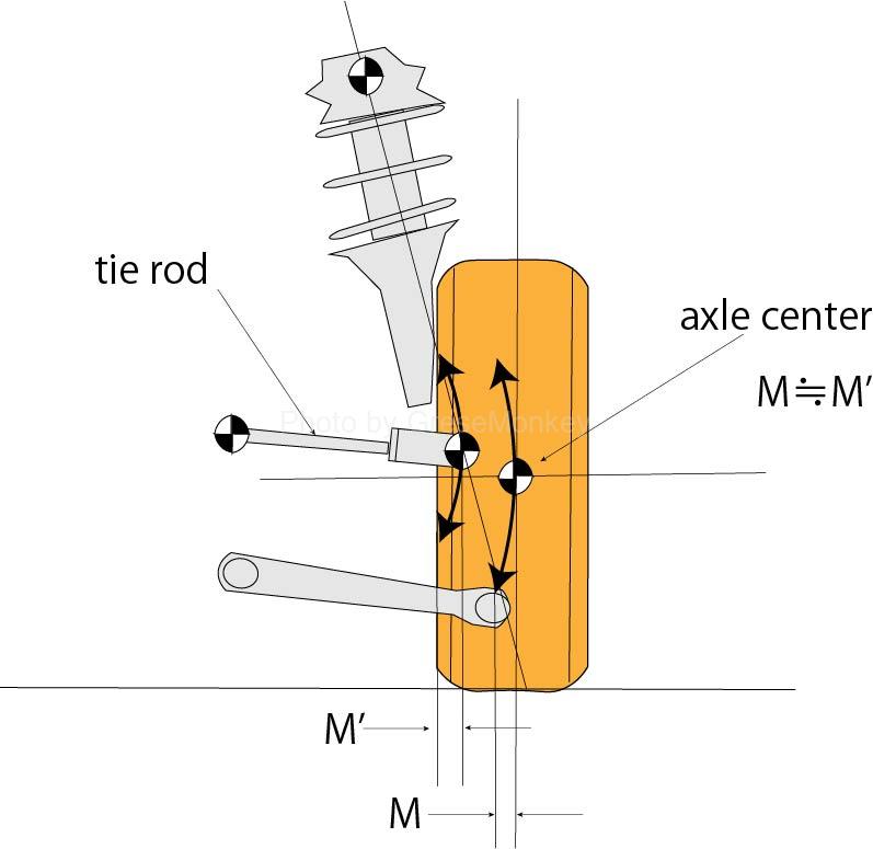
Figure 18: Toe change when going straight
- Toe change during steering
When there is a kingpin tilt angle, the vehicle body is lifted by steering, which changes the angle of the suspension arm and tie rod.
If the tire moves up and down in this state, the amount of movement of the axle center inward and outward and the amount of movement of the tie rod will differ as shown in Fig. 19, so in a car with a tie rod on the rear side of the tire, when bouncing (when the suspension spring is compressed) The toe changes to the toe-in side, and when rebounding (when the suspension spring is extended), the toe changes to the toe-out side.

Figure 19: Toe change during steering
Toe and unequal length tie rod
In the rack and pinion type steering, if the left and right tie rods have different lengths as shown in Fig. 20, even if the toe body is normal, if the steering wheel is facing the direction of travel, the left and right wheels will be in different directions. From FIG. 20, when the vehicle goes straight from this state, the rack stroke is longer on the left side and shorter on the right side. As a result, the lengths of A and B on the left and right, which are the sum of the tie rod length and the rack stroke, become equal, and straight running performance is maintained, but the center position of the steering wheel is misaligned, and when the steering wheel is turned left and right, left and right. Problems such as different cutting angles occur.
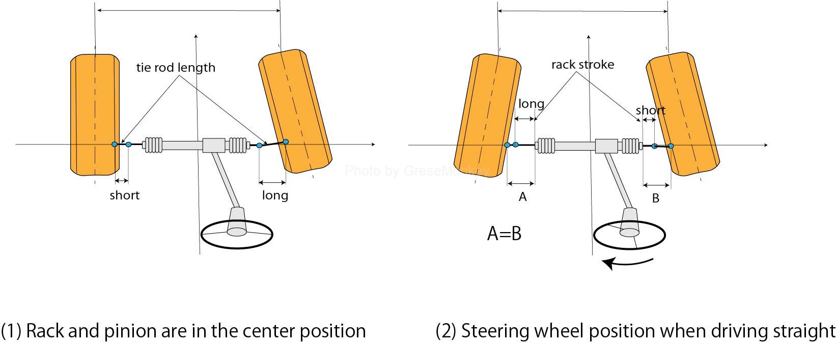
Figure 20: Rack and pinion type steering
In the ball nut type steering, the left and right turning angles are adjusted by the stopper (knuckle stopper cap), so even if the left and right tie rods have different lengths, the turning angle is not significantly affected. However, when traveling straight ahead, the toe of the left and right wheels is a composite as shown in Fig. 21, so the center of the steering wheel is out of order.
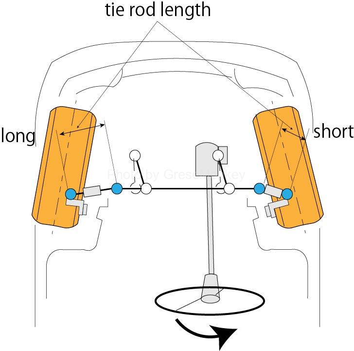
Figure 21: Ball nut type steering
Toe and all wheels going straight
When a car goes straight, the factor that determines the straight direction is the toe of the front, rear, left, and right wheels.
In particular, the toe of the rear wheels is important for straightness, and if this toe of the rear wheels is correct, the front, rear, left and right ruts are parallel and equidistant to the center line of all wheels in Fig. 22, and from the driver. The position of the handle you see is the center, which is ideal for alignment.
However, if the rear wheels are twisted or the alignment is changed and a problem occurs in the rear wheel toe, in an extreme case, the vehicle will run in the state shown in FIG. 23, which is not preferable in terms of steering stability. The traveling angle at this time is called a thrust angle (rear wheel change angle), and that direction is called a thrust line.
Generally, these measurements will be made with a dedicated four-wheel wheel alignment tester.
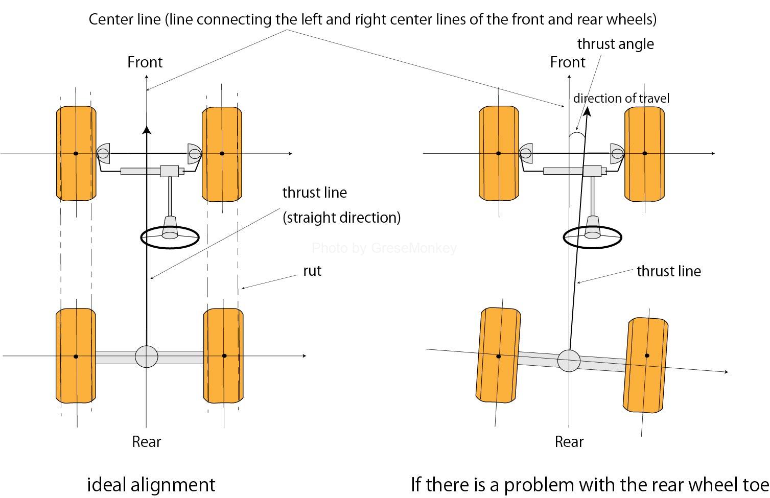
Figure 22: Ideal alignment ・ When there is a problem with the rear wheel toe
Sources/references
This site is based on the references listed below.
- Class 3 Automobile Chassis|Japan Automobile Maintenance Association Federation
- Vehicle Motion Performance and Chassis Mechanism | Takaaki Uno | Grand Prix Publishing