Subaru Impreza STi Manual Transmission Material

Vehicle specs
- Year: 2000
- Model: GDB
- Engine model: EJ207
- Transmission model: TY85
table of contents
- Vehicle specs
- Overview of 6-speed manual transmission and operating system
- Clutch and operating system
- About 6-speed transmission
- 4WD transfer device (center differential)
- Front differential
- Transmission / lubrication system
Overview of 6-speed manual transmission and operating system
In order to improve driving performance by transmitting and controlling the torque of the STi specification DOHC high power turbo engine (maximum output 206kW-maximum torque 373Nm), a full-time 4WD 6-speed manual transmission has been adopted to improve the operation system. There is. As an operation system, in order to cope with the high power of the engine, the starting performance is improved by increasing the clutch capacity and improving the clutch oil pressure gauge.
Main features of full-time 4WD 6-speed manual transmission
- A double cone synchromesh mechanism is used for 1st, 3rd and reverse, and a triple cone synchromesh mechanism is used for 2nd speed to improve durability and operability.
- The main case is a split type to improve rigidity.
- The reverse gear always uses a meshing method.
- The oil pump is located in the main case.
- The front differential is equipped with a torque-sensitive cam type LSD, and the center differential is equipped with a driver’s control type or viscous coupling type.
- The gear shift system uses a floor shift parallel link type and slider type reverse erroneous operation prevention mechanism.
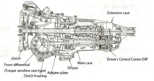
Figure 1: Inside the transmission
Clutch and operating system
The clutch capacity of the clutch disc has been increased from the conventional outer diameter x inner diameter: 230 mm x 150 mm to 240 mm x 160 mm. The clutch operation system is a hydraulic pull type, and an orifice is provided in the hydraulic circuit to prevent sudden clutch engagement.
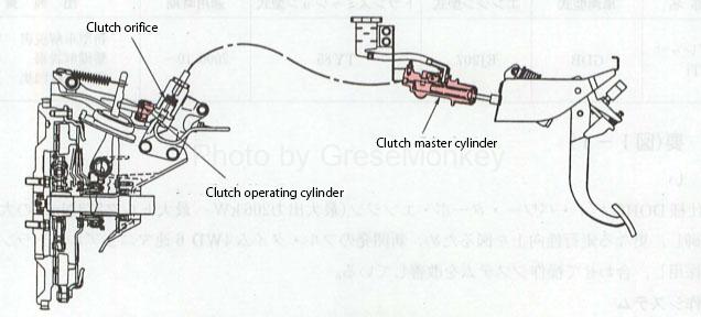
Figure 2: Hydraulic clutch control system
Hydraulic clutch control system
The clutch master cylinder is a compensatory type, and a clutch orifice is added to the hydraulic circuit between the clutch master cylinder and the clutch operating cylinder to reduce the shock torque when the clutch is connected, and inside the orifice. A compression spring made of a shape memory alloy is provided in the hydraulic circuit to ensure that the clutch operation delay due to the orifice does not occur at low temperatures.
- Operates at room temperature
The clutch orifice is integrated into the clutch operating cylinder and consists of an orifice retainer, an orifice valve and a compression spring. The orifice valve is usually pressed against the body with compression spring No1.
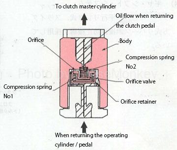
Figure 3: Clutch orifice operates at room temperature
- Operates at low temperatures
At low temperatures, the shape memory alloy compression spring No. 1 contracts to eliminate the spring action, and the compression spring No. 2 presses against the orifice retainer to ensure a sufficiently wide oil passage.
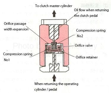
Figure 4: Clutch orifice operating at low temperatures
About 6-speed transmission
Specification drawing
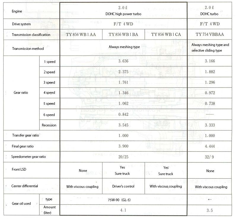
Figure 5: Transmission specification diagram
Speed change mechanism
The transmission mechanism has two main transmission gears with a main shaft and a drive pinion shaft arranged in parallel, with 6 forward and 1 reverse gears that are always engaged, and the reverse reverses the direction of rotation via the reverse idle gear. It is a method to make.
Helical gears are used for all gears, and the gear specifications and tooth width have been reviewed and the distance between the centers of the main transmission gears has been expanded to 85 mm to improve gear strength.
- Synchromesh mechanism
The synchromesh mechanism adopts multi-cone synchro for 1st to 3rd speed and reverse to reduce the shift operation force. The reverse synchro is located in the reverse idle gear section.
In addition, asymmetric gear dogs are used for 2nd to 6th gears to improve operability.
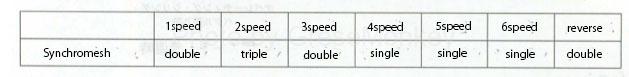
Figure 6: Transmission gear and cone types
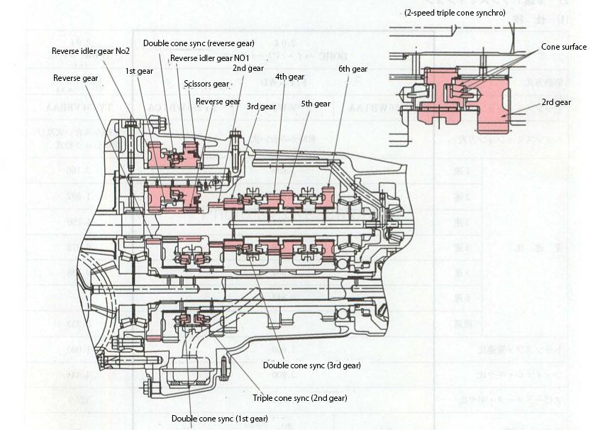
Figure 7: Inside the synchromesh mechanism
- Reverse gear
As the reverse gear is constantly engaged, a scissors gear is installed in the reverse idler gear No. 1 to improve quietness.
The reverse idle gear consists of a reverse idle gear N01, a scissors gear, a spring friction plate and a snap ring.
By sandwiching the drive side gear between the scissors gear and the idler gear that have received the spring force, the backlash of the gear is set to 0 and rattling due to the meshing of the gear is prevented.
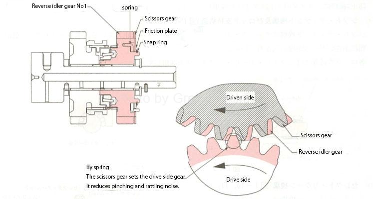
Figure 8: Reverse gear
Shift and select mechanism
The shift pattern is a floor shift system with 6 forward steps and 1 backward step, and friction is achieved by adopting slide ball bearings for each rod support and mounting a ball built-in plunger on the shift detent mechanism. Has been reduced and operability has been improved.
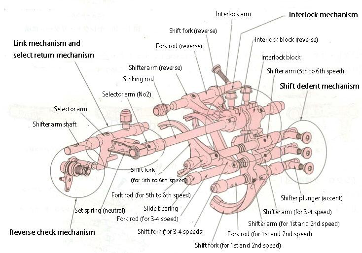
Figure 9: Shift fork
The select mechanism unit realizes a short select stroke as a parallel link method. The interlock (double meshing prevention) mechanism adopts a slider pull-up type as a reverse check (reverse malfunction prevention) mechanism as a block type.
- Shift dedent mechanism and rod support structure
The shift dedent mechanism uses a check ball to prevent the gear from coming off. A small ball is embedded in the back of the check ball part.
Slide ball bearings are used for each rod support.
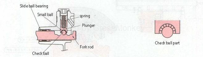
Figure 10: Shift dedent mechanism (prevention of gear disengagement)
- Select / return mechanism
The select / return mechanism consists of a shifter arm shaft, selector arms (No. 1 and 2), a striking rod and a set spring (neutral).
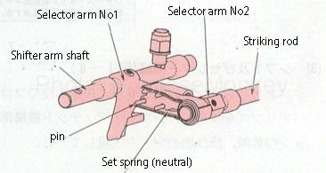
Figure 11: Select return mechanism
The select / return force corresponds to the movement of the selector arm, and the set spring (neutral) is expanded by the fulcrum on the selector arm, and is generated by the return force of the spring.
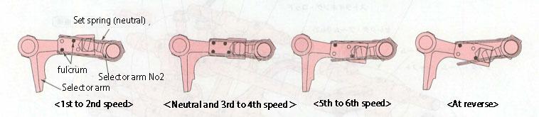
Figure 12: Selector arm movement
- Interlock mechanism

Figure 13: Interlock mechanism
-
- Normal selection
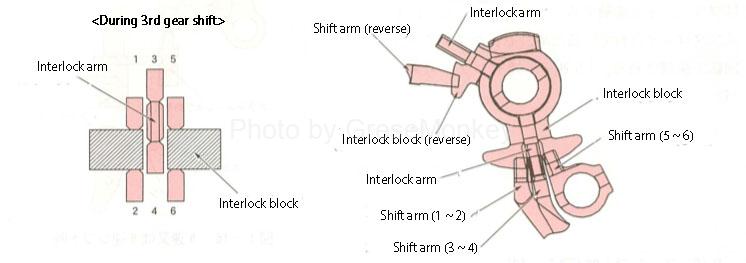
Figure 14: Normal selection
-
-
During an intermediate shift (during double engagement)
-
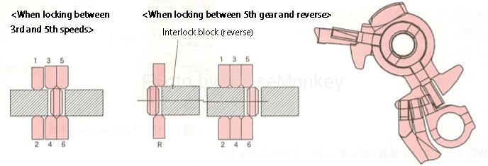
Figure 15: During an intermediate shift
- Reverse check mechanism

Figure 16: Reverse check mechanism
-
- When shifting to 5th or 6th gear
When selected to the 5th or 6th speed side, the selector arm comes into contact with the plunger. Since the plunger is interlocked by the pins, the rotation of the selector arm is restricted.
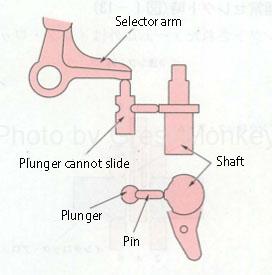
Figure 17: 5th or 6th gear shift
-
- At the time of reverse shift
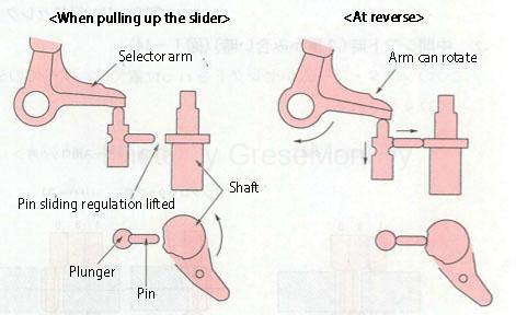
Figure 18: During reverse shift
4WD transfer device (center differential)
Driver’s Control Center Differential
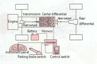
Figure 19: Driver’s Control Center Differential
- When an electric current flows through the electromagnetic coil, a magnetic field is generated between the electromagnet, the differential case, the pilot clutch, and the armature.
- The pilot clutch and armature are attracted to the electromagnet by the next induction action, and the rotational torque (pilot torque) of the differential case rotates the cam NO2.
- When the cam NO2 rotates, the rotation is different from that of the cam NO1, so the ball rolls and a thrust force is generated, and the planetary gear that can move in the axial direction is slid to press the main clutch to generate the differential limiting torque.
- Since the strength of the magnetic field increases in proportion to the amount of current flowing, the differential limiting torque also increases in proportion to the amount of current. In addition, the amount of current can be changed in 5 stages by the driver operating the control switch.
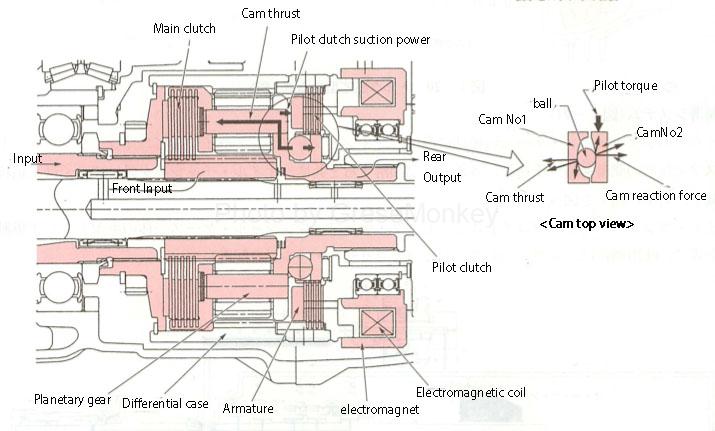
Figure 20: Driver’s Control Center Differential operation
Front differential
Torque sensitive cam type LSD
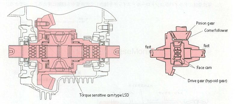
Figure 21: Torque-sensitive cam LSD
Transmission / lubrication system

Figure 22: Transmission lubrication system