Automotive meter basics
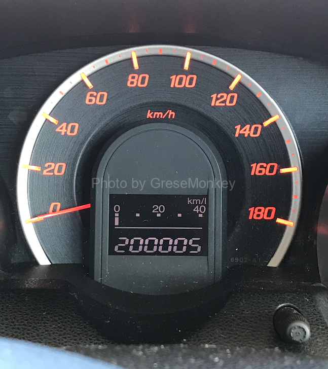
Among the gauges in the combination meter, the oil pressure gauge, fuel gauge, water temperature meter and charging display device (charging lamp) are combined with a sensor unit that detects various measurement values and a receiver unit displayed on drivers.
These units are divided into several types of operating mechanisms, but are used in combination according to their applications.
Table of Contents
- Various gauge connection method
- Regiver unit
- Operation coil type fuel gauge operation
- Store needle -type Regiver unit
- Fuel level indicator
Various gauge connection method
The gauge using an electric receiver unit and a sender unit is connected in a series of receiver units and Sender unit in a single wiring, and is used for 12V or 24V power supply. Therefore, this voltage differs depending on the gauge method, not a 12V or 24V voltage on the receiver unit or the Senda unit, so if you do not handle it after knowing the gauge method well, the parts are damaged. It is important to note that you make an incorrect judgment during trouble or trouble shooting.
A circuit that combines a resistance type Senda unit and a bimetal receiver unit
In a gauge in a form in which the receiver unit and the Senda unit are tied in series, there is no mechanism to control the time when current flows on the Senda Unit, so the current change of the electric heating line of the receiver unit becomes an error. , Voltage compensation is required.
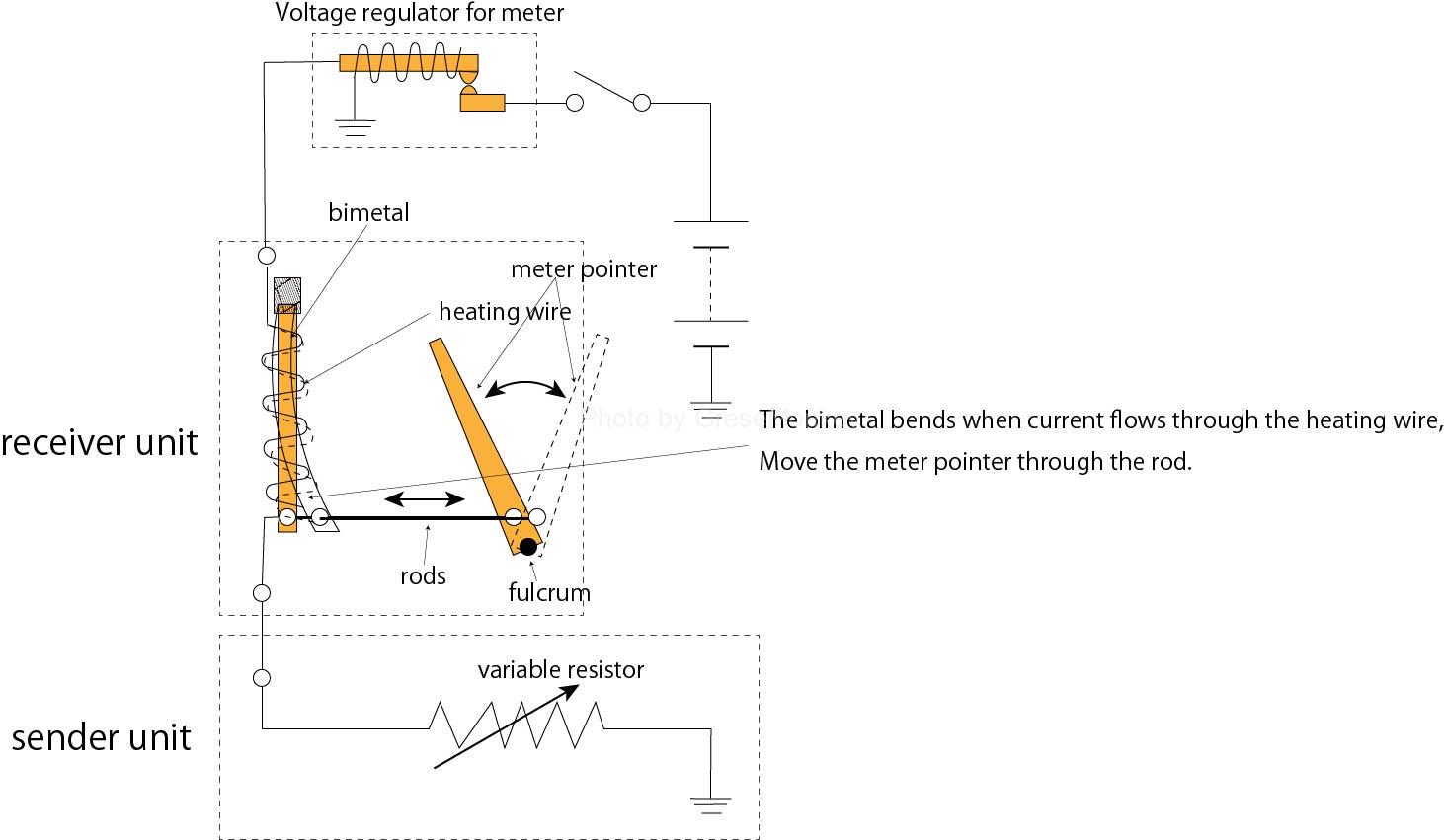
Figure 1: Activation of bimetal and resistance meter
For this reason, a voltage regulator for meter is provided on the power side of the receiver unit as shown in FIG. 1, so that an error is not generated.
The voltage regulator for the meter is connected to each gauge as shown in FIG.
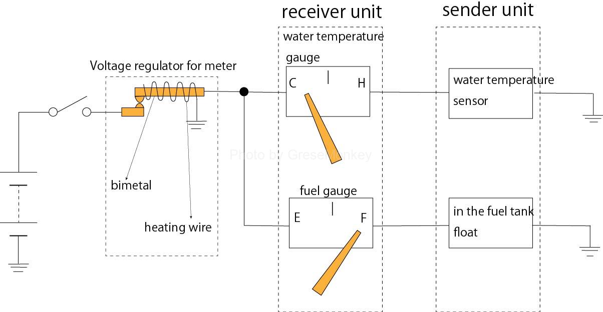
Figure 2: Connection of voltage regulator for meter (contact type)
In this operation, when the key switch is turned on, the current flows to each gauge circuit through the contact of the voltage regulator. At the same time, the electric wire of the voltage regulator also flows, and the bimetal is heated, and after a certain amount of time, the bimetal is curved and the contact is disconnected, and the current to the gauge circuit is disconnected.
When current does not flow to the electric heating line of the voltage regulator, the bimetal cools down, returns to the original state, the contact is closed, and the current flows to the circuit again. This operation is repeated while the key switch is turned on, so the gauge circuit is periodically intermittent.
Therefore, the opening / closing cycle of the voltage regulator changes in accordance with the fluctuations of the power supply voltage, and the circuit is supplied to a certain amount of electricity, and the receiver unit prevents instruction errors without being affected by the voltage fluctuation. be able to.
Most of the meter contact voltage regulators are mostly integrated with the receiver unit. It may be assembled in a case made of insulator, and may be used separately and used.
A circuit that combines a resistance type Senda unit and an intersection coil -type receiver unit
About fuel gauge as shown in Fig. 3
Figure 3: Configuration of intersection coil type fuel gauge
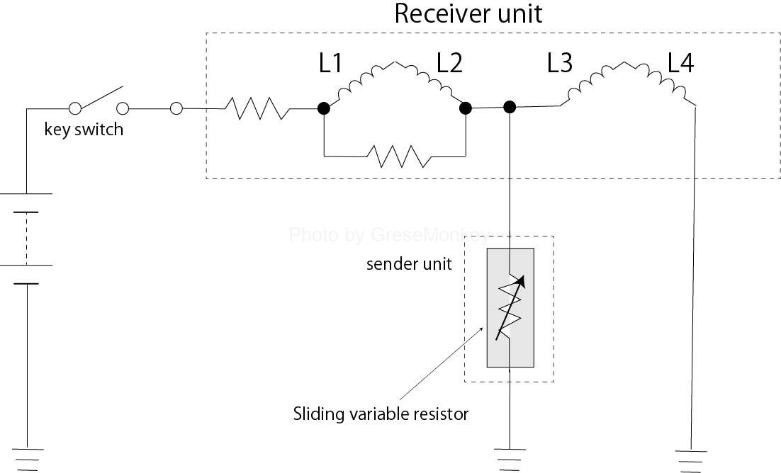
Figure 4: Driving circuit of intersection coil type fuel gauge
As shown in FIG. 4, the coil L1 and L2 on the other of the Senda unit and the receiver unit are connected in series, while the other coil L3 and L4 are connected in parallel with the Sender Unit.
The method of this sender unit is moved by the effects of the rotator made of magnets and the effects of the synthetic magnetic field generated by the coils wrapped at a right angle to each other. For this reason, even if the power supply voltage fluctuates, both magnetic fields that make both of the magnetic fields need to increase or decrease at the same ratio, so that the ratio of this magnetic field is the same, the instructions of the guideline have a circuit structure that does not cause an error.
Receiver unit
The receiver unit crosses the coil around the rotors (magnet) and is operated by the magnetic field.
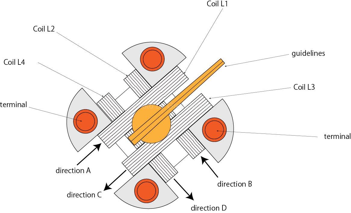
Figure 5: Winding direction of intersection coil
As shown in FIG. 5, L1 and L3 are wrapped upside down in the coaxial to the A direction and C direction, and L2 and L4 are wrapped in the opposite direction between the B direction and the D direction. These coils generate a magnetic field that operates the rotator.
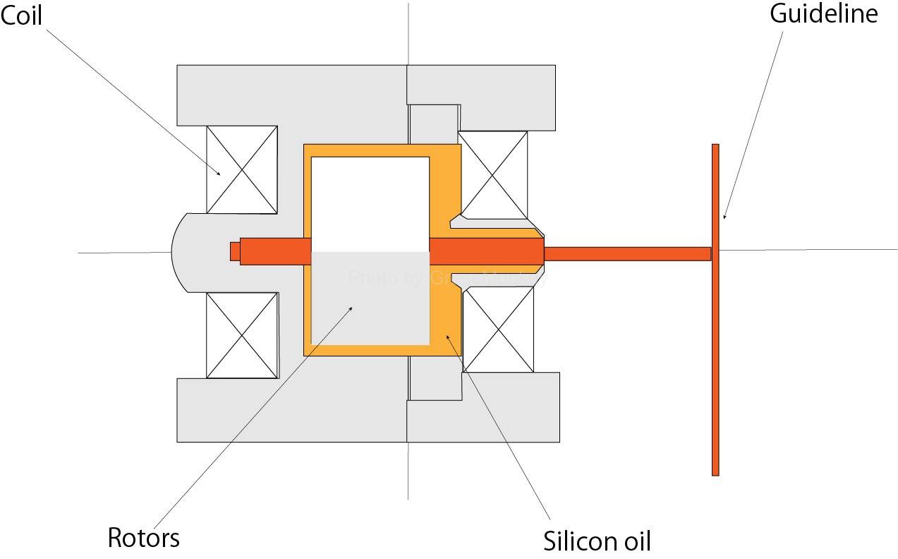
Figure 6: cross section of intersection coil type gauge
In this meter, silicone oil is injected around the rotors as shown in FIG. 6 to control the movement of the rotor. (By balancing with the power of the magnetic field, it maintains the movement and balance of the rotors.)
Operation coil type fuel gauge operation
When the RS resistance value is 0
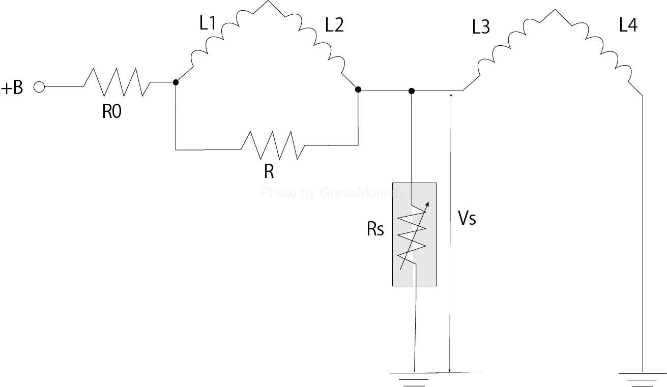
Figure 7: Driving circuit diagram of intersection coil type fuel gauge
When the resistance of the RS in FIG. 7 is 0, the voltage vs is also 0 potential, the composition circuit is L1 → L2 → ground, and the current is exciting only in L1 and L2.
Therefore, the guideline of the rotor stops at the location of the synthetic magnetic field of L1 and L2.
L1 and L2 intersect 90 degrees, but L1 has a larger number of winding compared to L2, so the magnetic field of L1 is larger than L2, and the convergin guideline approaches the L1 magnetic field. Stops at the position of the synthetic magnetic field (angle θ1) in FIG. 8.
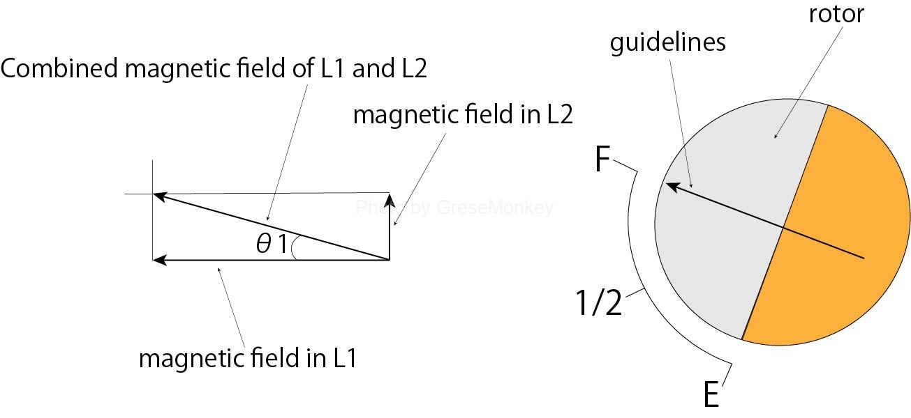
Fig. 8: Activation when the resistance value of RS is 0
When the resistance value of RS rises
Figure 7: Driving circuit diagram of intersection coil type fuel gauge
When the resistance of the RS rises, the voltage VS also rises in proportion, and the circuit configuration is L1 → L2 → L3 → L4 → ground at the same time as L1 → L2 → RS → Earth.
Therefore, since the current flows to all the coils, L1, L2, L3, L4 are exciting.
L1 and L3 have the opposite of the winding direction of the coil, so the magnetic field of L3 acts in the direction of reducing the L1 magnetic field.
L2 and L4 also have the opposite of the winding direction of the coil, so the L2 magnetic field acts to reduce the L4 magnetic field.
When the movement of the guidelines of the receiver unit is regarded in 0 ° to 180 ° units (half scale), the synthetic magnetic field of all coils is as shown in FIG. ) Stop at the rotated position.
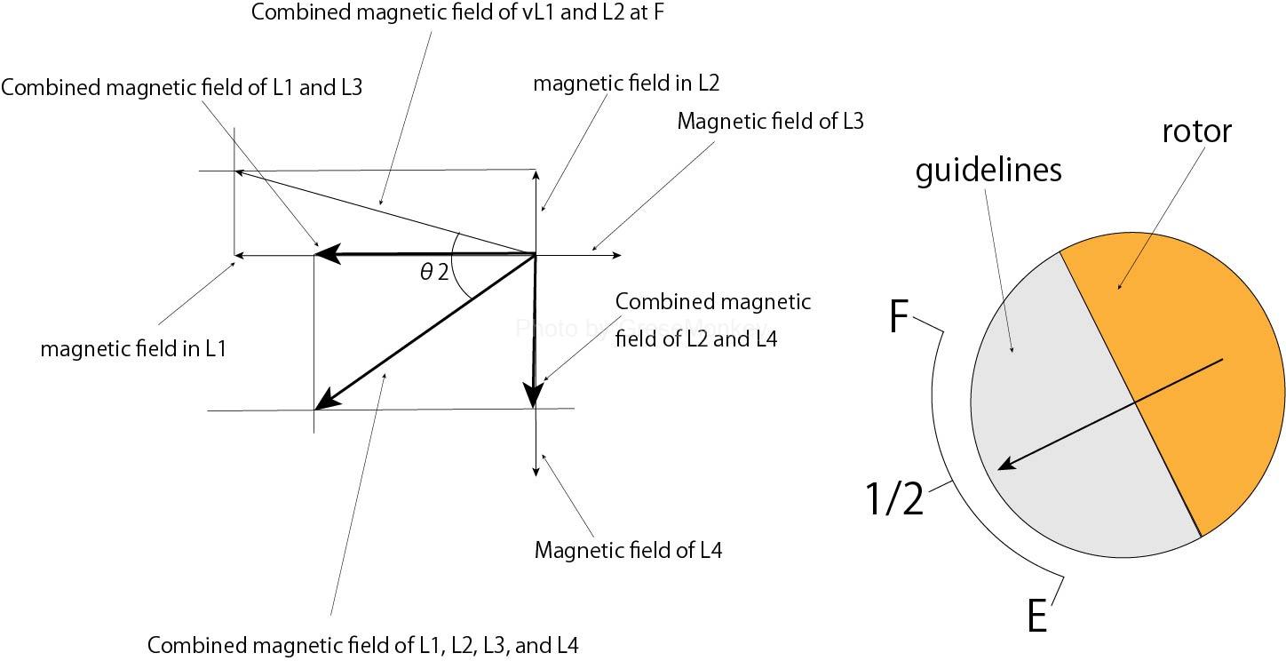
Fig. 9: Activation when the resistance value of RS rises
Store needle -type Regiver unit
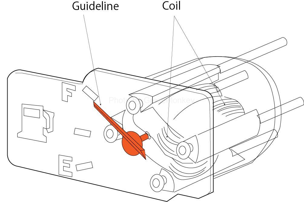
Figure 10: Store needle receiver unit
In general, the gauge is in a state where each guideline has returned to its original position unless the key switch is turned on and the current flows. In the fuel gauge, it is convenient if the remaining amount at that time can be confirmed as shown in FIG. 10, regardless of the key switch.
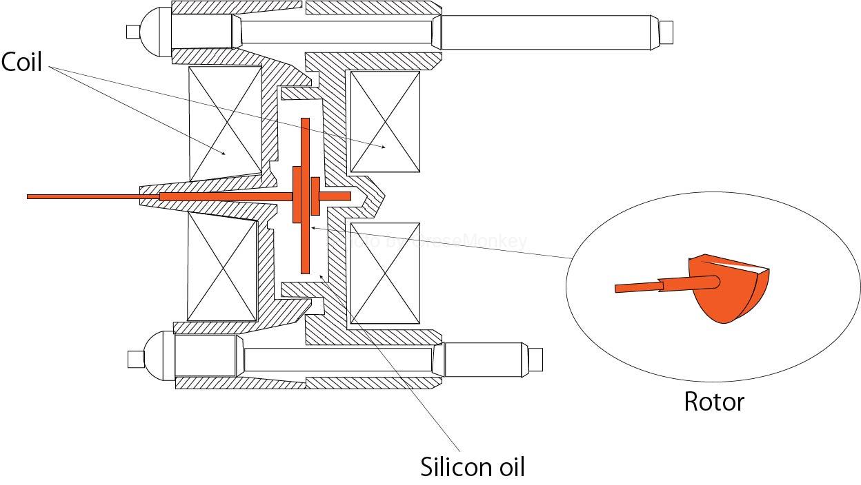
Figure 11: The cross section of the needle -type receiver unit
Therefore, the part where the rotor of the coil -type receiver unit is placed is a sealed case as shown in FIG. 11, and if the viscosity silicone oil is included in it, the silicone oil is viscous even after turning off the power. The rotors are stopped as they are, and the guidelines are indicated without returning. A receiver unit with such a structure is placed and is called a needle -type receiver unit.
Fuel level indicator
The fuel -level indicator is composed of indicator lamps and thermistors as shown in FIG. 21, lighting the lamp when the fuel remaining in the fuel tank decreases, giving a warning to the driver.
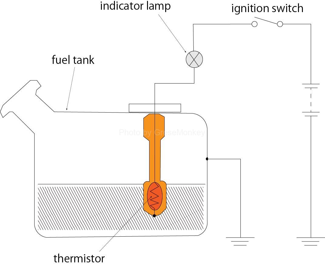
Figure 12: Fuel -level indicator
If there is a lot of fuel in the tank, the temperature is low because the thermista is immersed in gasoline.
Therefore, the resistor of the thumbista is large, and the current flows through the circuit is small, so the lamp does not light.
When the gasoline in the tank is reduced, and when the thermista is exposed outside the gasoline, the temperature of the thermista rises and the resistance is reduced, so the lamp lights up.
Generally, thermistors are used in fuel sensor units.
Sources/references
This site is based on the references listed below.