Operation and structure of automobile speedometer
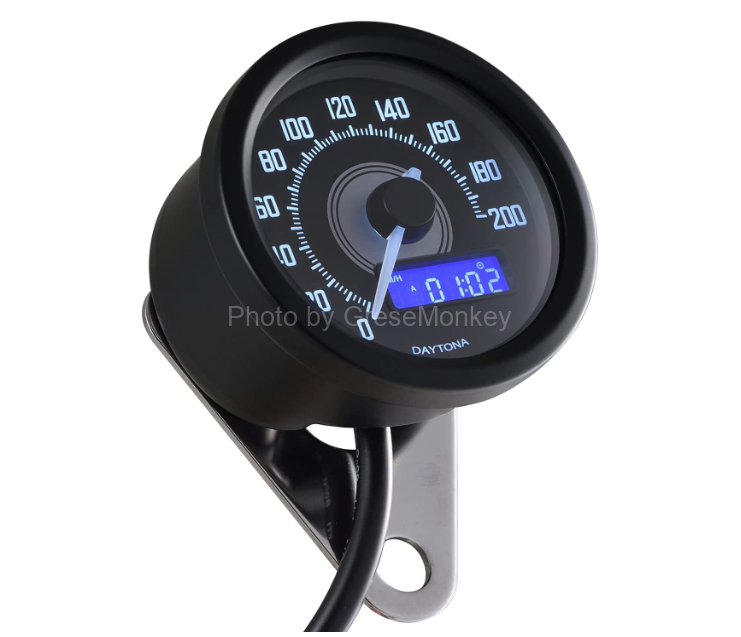
The combination meter has a speedometer, tachometer, fuel gauge, water temperature gauge, various indicators, etc. arranged in one panel so that the driver can check the operating status of each part of the car at a glance. A combination meter generally has a structure that mechanically indicates numerical values and quantities with pointers.
Table of Contents
- Electric speedometer
- Vehicle speed sensor
- Mechanism of speed display
- Working principle of cross-coil meter
- Cumulative mileage
Electric speedometer
The electric speedometer is a cableless speedometer that does not use cables, and consists of a vehicle speed sensor that detects vehicle speed, a cross-coil speedometer, and a pulse motor-type odometer and trip meter. It is installed and the speedometer is operated by the electric signal obtained from it.
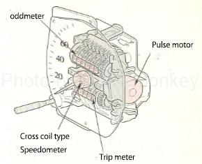
Figure 1: Electronic speedometer
The meter section in Fig. 1 includes a cross-coil speedometer that moves the hands, an electronic circuit that applies current to the cross-coil, and an odometer and trip meter that integrate the distance traveled.
Vehicle speed sensor
Many vehicle speed sensors of electric speedometers use a magnetic induction element (MRE: Magnetic Resistance Element).
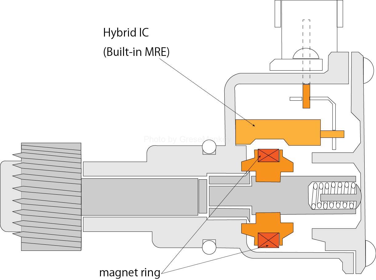
Figure 2: Magnetoresistive element (MRE) speedometer sensor
As shown in Fig. 2, this sensor consists of a hybrid IC with a built-in magnetoresistive element and a magnet ring driven by the drive gear (final speed detection) on the output shaft of the transmission.
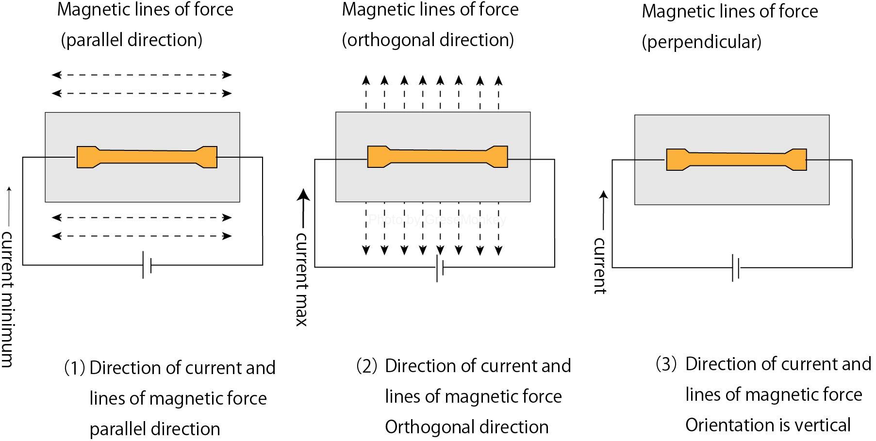
Figure 3: Properties of a magnetoresistive element (MRE)
A magnetoresistive element (MRE) has the property that the magnitude of resistance changes as the magnetic lines of force change with respect to the direction of the current, as shown in Fig. 3.
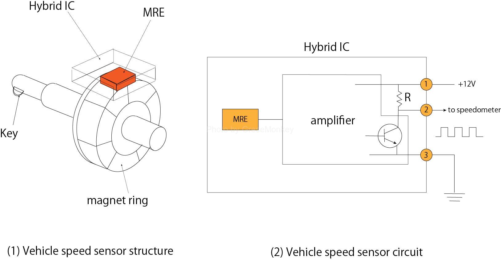
Figure 4: Vehicle speed sensor structure
In addition, since the MRE is arranged around the multipolar magnet ring as shown in FIG. 4, the direction of the magnetic lines of force changes according to the rotation speed of the ring, and a pulse signal is generated.
This signal is converted to a digital signal by the comparator and transistor in the amplifier and sent to the electronic circuit of the speedometer from the ② terminal of (2) in Fig. 4.
The output of the vehicle speed sensor is a signal with a period of 4 pulses per rotation of the magnet ring.
Mechanism of speed display
In the cross-coil speedometer, when the signal from the vehicle speed sensor is input to the electronic circuit as shown in Fig. 5, this IC counts the pulses of the signal, and the magnitude and direction of the current flowing through the cross-coil according to the vehicle speed. is changed, and the needle (magnet) is swung in the direction of the synthetic magnetic field formed thereby to display the speed.
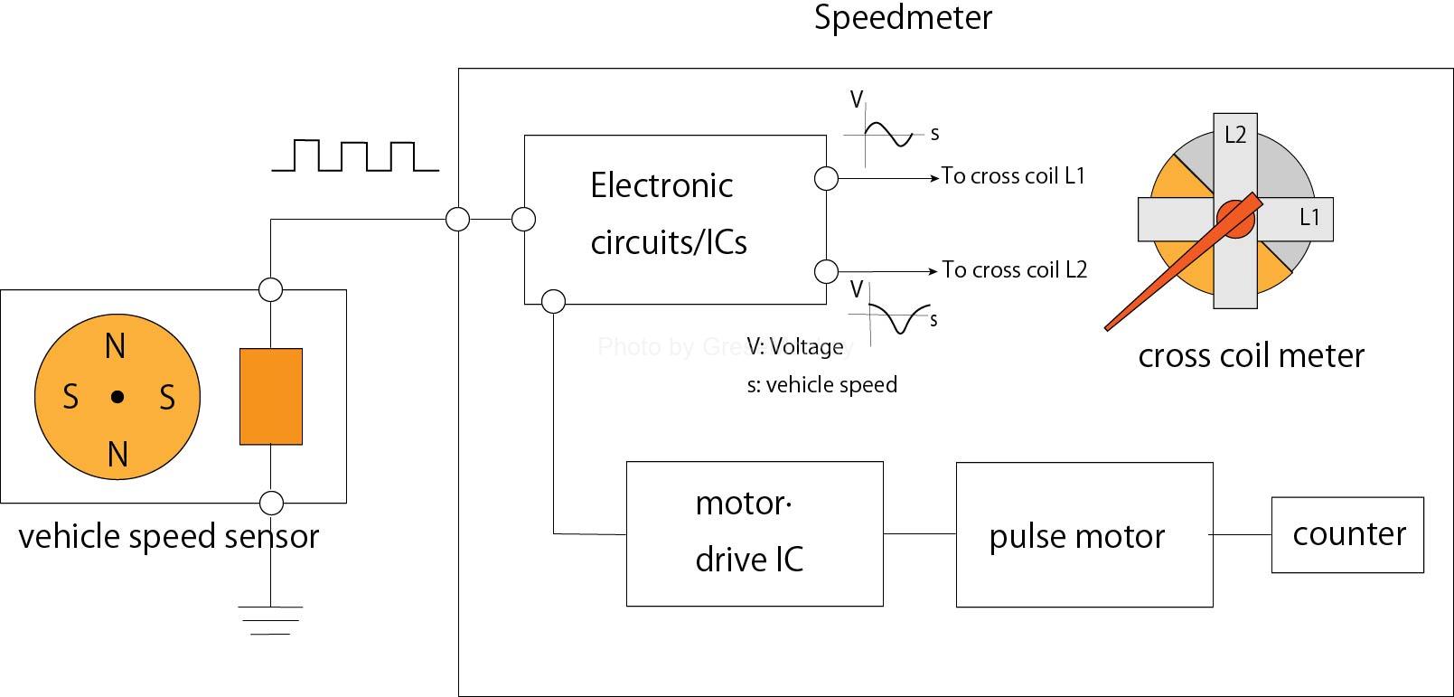
Figure 5: Cross-coil speedometer configuration
Working principle of cross-coil meter
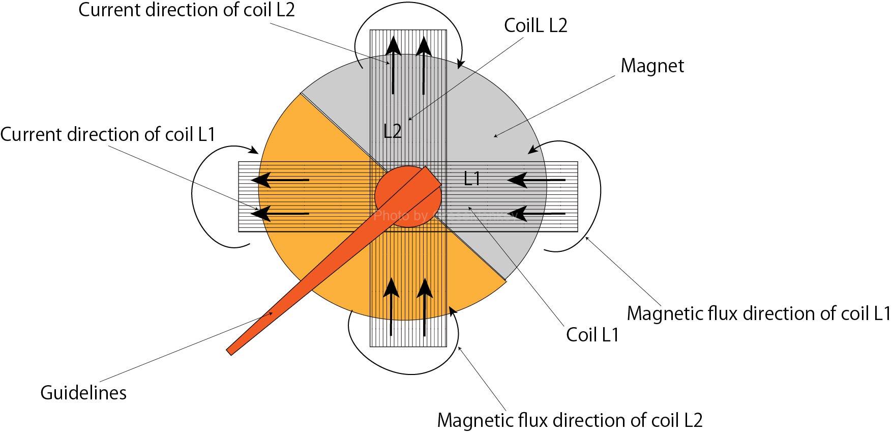
Figure 6: Cross-coil meter
A cross-coil meter has two coils wound 90 degrees off-set on the outside of a magnetic rotor, as shown in Figure 6.
As a result, from the electronic circuit, the magnitude and direction of the current flowing through the coils L1 and L2 change like a sinusoidal waveform in conjunction with the vehicle speed. Actually, the graph of the relationship between the current and the vehicle speed is obtained by offsetting the phase of the waveform by 90 degrees as shown in (1) of FIG.
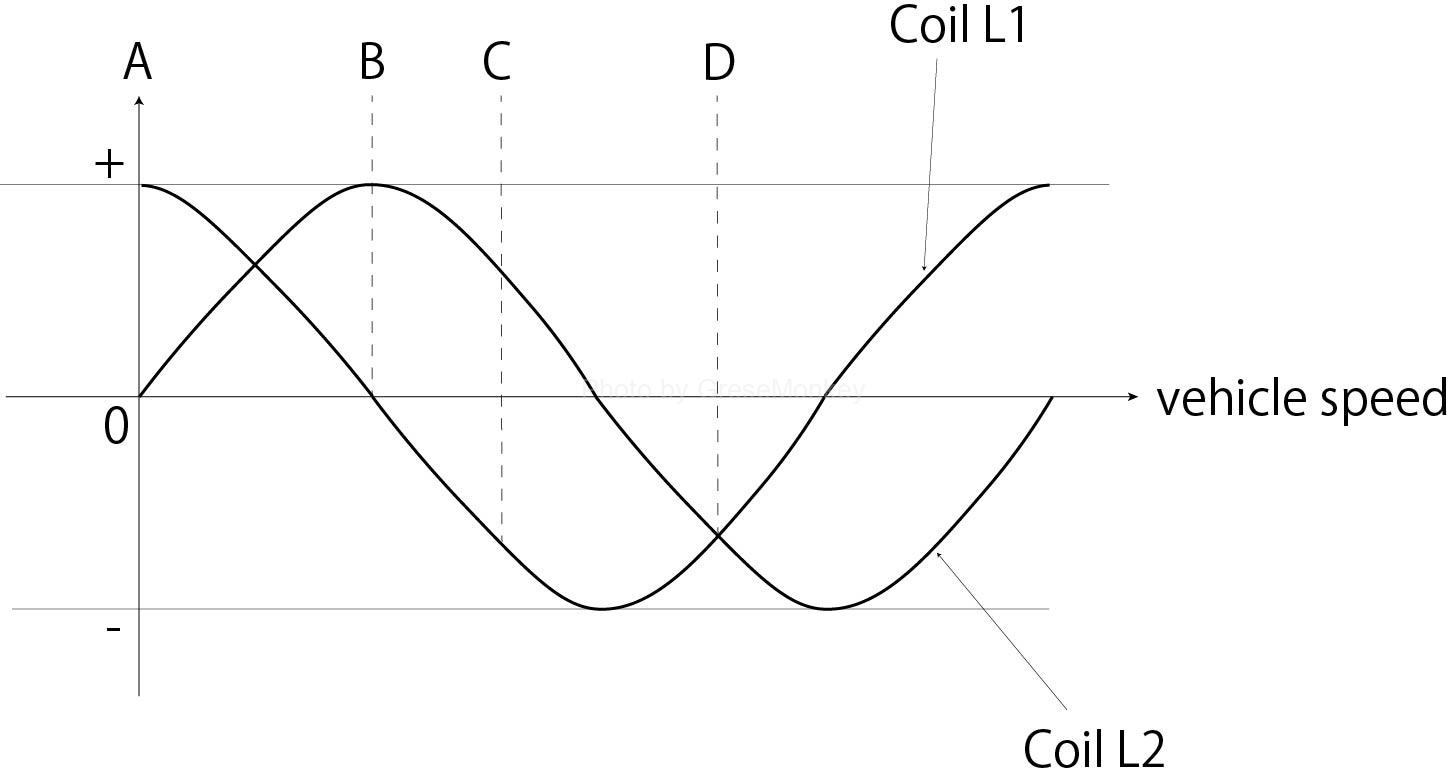
Fig. 7 (1): Relationship between coil current and vehicle speed
In the cross-coil type meter, the direction and magnitude of the magnetic field generated by each coil are changed, and the pointer indicates the direction of one magnetic field or a composite magnetic field of two-way magnetic fields as shown in Fig. 7 (2) A to D. That is, it points in the direction of the vector in which the forces are balanced.
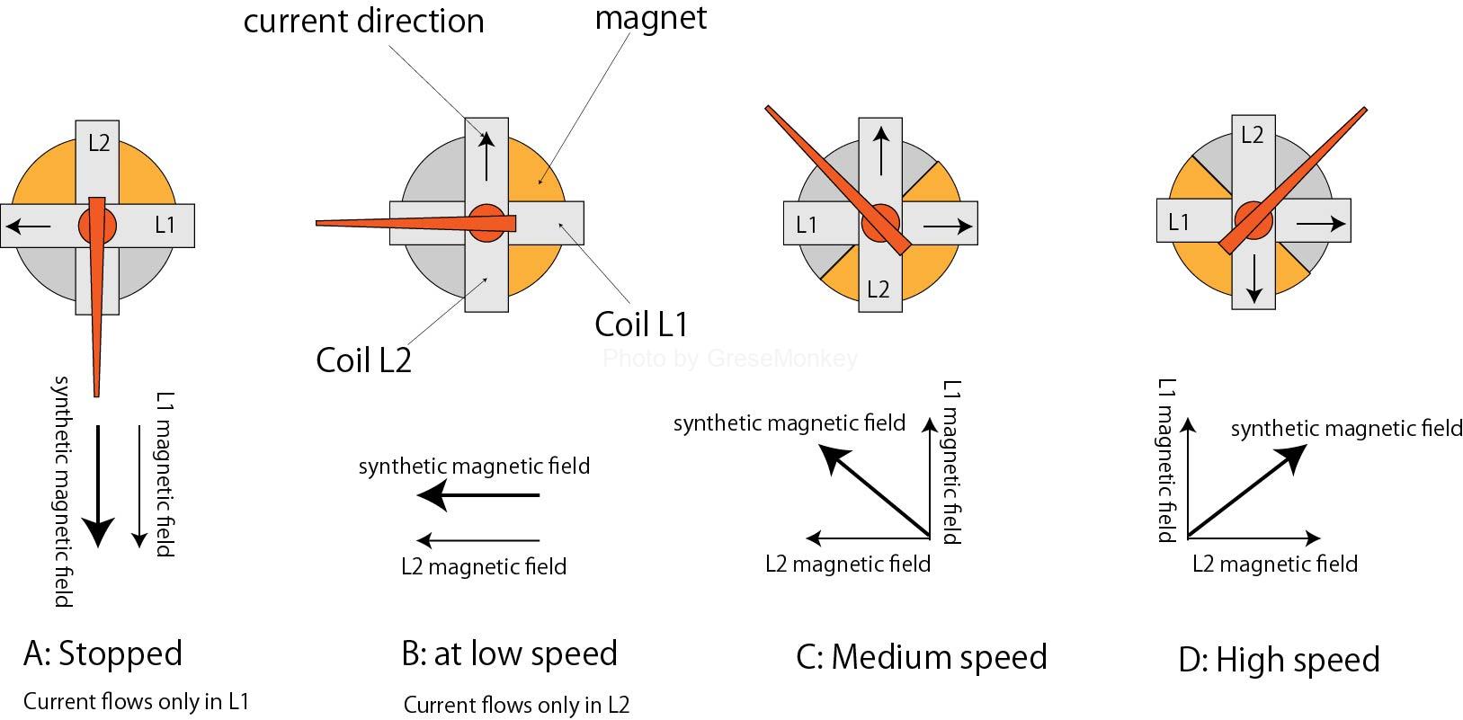
Figure 7(2): Pointer direction at each speed
Cumulative mileage
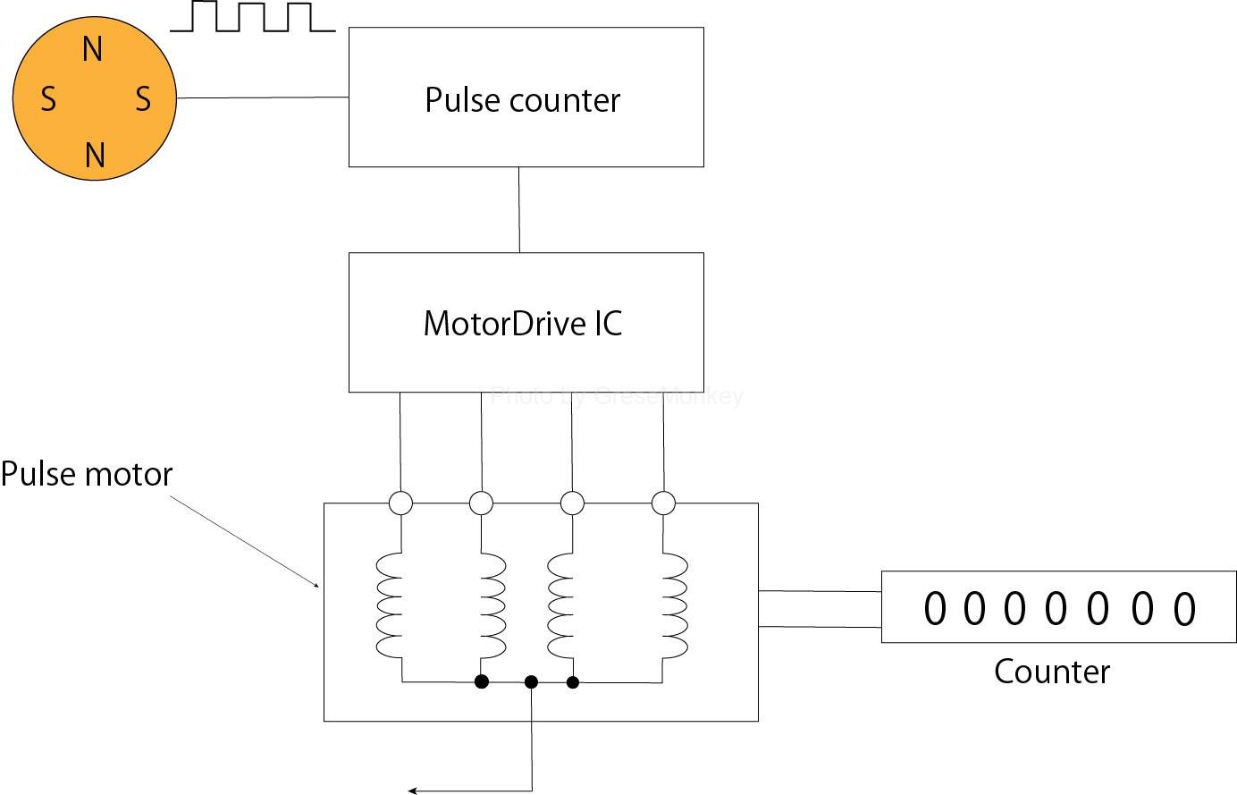
Figure 8: Pulse motor drive circuit
The driving circuit shown in Fig. 8 integrates the signal from the vehicle speed sensor with the rotating pulse motor and odometer to determine the traveled distance.
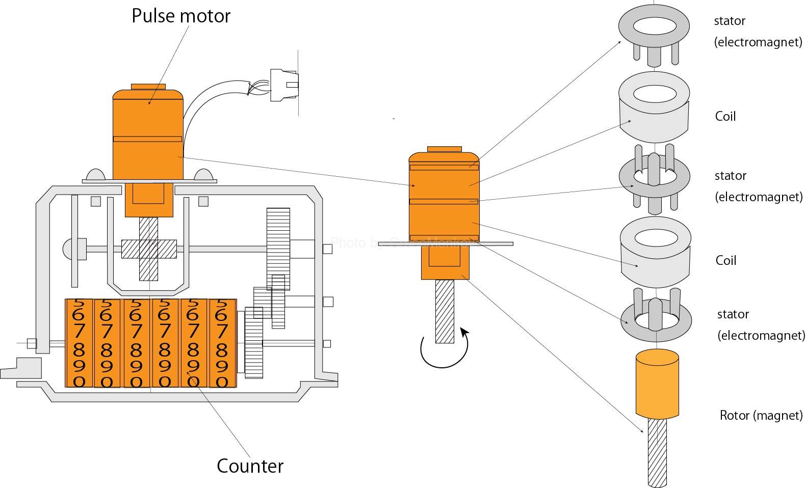
Figure 9: Pulse motor type total rangefinder
As shown in Fig. 9, a pulse motor consists of two layers of coils, a stator (electromagnet), and a rotor (magnet). The motor rotates intermittently by 15 degrees, and receives pulse signals from the vehicle speed sensor. Then, the motor drive IC energizes each coil and rotates according to the number of pulses to drive the odometer and trip meter.
Sources/references
This site is based on the references listed below.