Basic performance of diesel engine
Rudolf Diesel invented the four-stroke engine in 1892, which used pulverized coal as fuel and self-ignited in compressed air. In 1897, Diesel completed a practical diesel engine that used heavy fuel oil and injected it with high-pressure air. After this invention, the diesel engine was named after him.
Early diesel engines were mainly used in fixed equipment and ships, but in 1927 Bosch commercialized an injection pump with directional injection, which led to the development of a high-speed diesel engine, which was also put into practical use as an automobile engine. Ta.
In Japan, research and production of diesel engines began in the 1930s, with a 6-cylinder air-cooled diesel engine with a total displacement of 8 liters completed in 1936, and a 5.1-liter 6-cylinder water-cooled automotive diesel engine in 1939. , was put into practical use. These engines aim to increase speed and output, while at the same time attracting attention for reducing emissions of harmful substances such as NOx (nitrogen oxides) and PM (particulate matter).
Note: The main component of PM is black smoke and a mixture of various components.
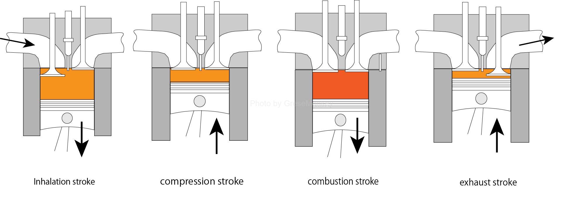
The piston and cylinder diagram for one cycle is shown.
Recently, common rail type and unit injector type high pressure fuel injection devices have been adopted. These devices atomize the fuel by increasing the injection pressure and increase the total surface area. This atomization allows the fuel to contact the surrounding air and the heat of compression more effectively, improving combustion conditions and suppressing PM generation. In addition, improved ignition performance shortens ignition delay and suppresses NOx generation.
Here, we will explain the general basics of diesel engines used in automobiles, such as characteristics such as combustion method and combustion output, valve timing and exhaust gas characteristics, when looking at the engine itself. think.
The general content is the basics of diesel engine combustion methods and the basic settings of valve timing to achieve them. Thermal efficiency, pressure, power, loss, volumetric efficiency brought about by engine combustion, and characteristics during engine combustion. In addition, there are disadvantages such as diesel knock, exhaust gas characteristics, and countermeasures.
Table of contents
- Diesel engine combustion method
- Valve timing
- Thermal efficiency
- Average effective pressure
- Indicated power and net power
- Engine losses
- Volumetric efficiency and filling efficiency
- Diesel engine combustion
- Diesel Knock
- Exhaust gas
Diesel engine combustion method
The combustion system of a diesel engine is a combination of a constant pressure cycle diagram (diesel cycle) and a constant volume cycle diagram (Otto cycle) in a cycle diagram that expresses the relationship between P (pressure in the cylinder) and V (volume in the cylinder). In the combined cycle diagram (Sabate cycle), it is a method that represents the combustion state under constant pressure and constant volume.
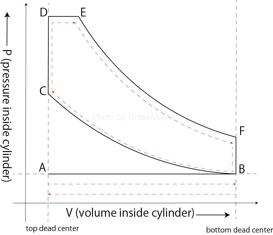
Figure 1: P-V diagram of combined cycle (Sabate cycle)
Figure 1-1 is a P-V diagram of the combined cycle (Sabate cycle). This cycle shows the process of intake-compression-combustion-exhaust.
inhalation
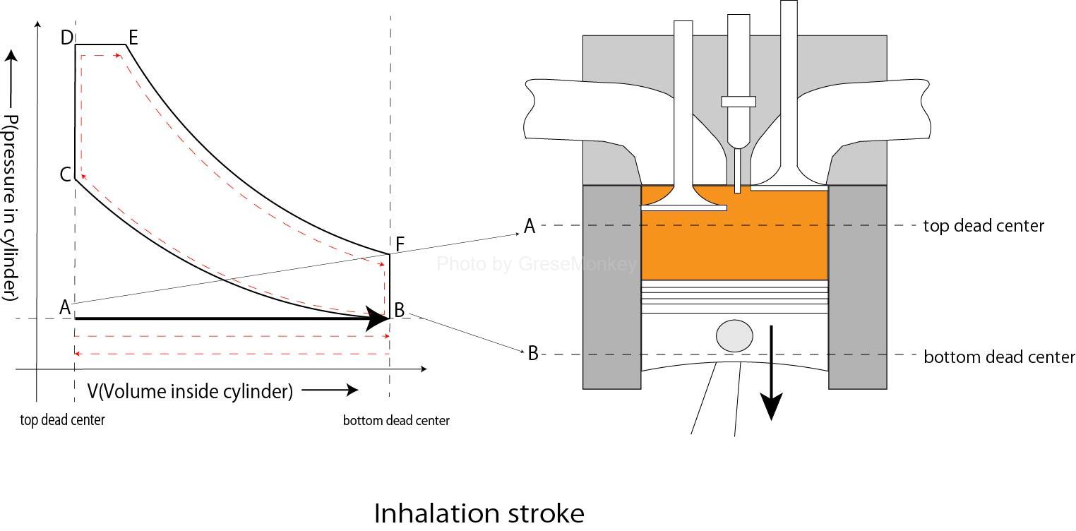
Inhalation process
At point A, the piston is at the top dead center position and suction is about to begin toward point B. As the piston descends, the volume inside the cylinder increases, and at point B, the piston is at the bottom dead center. Located in
compression
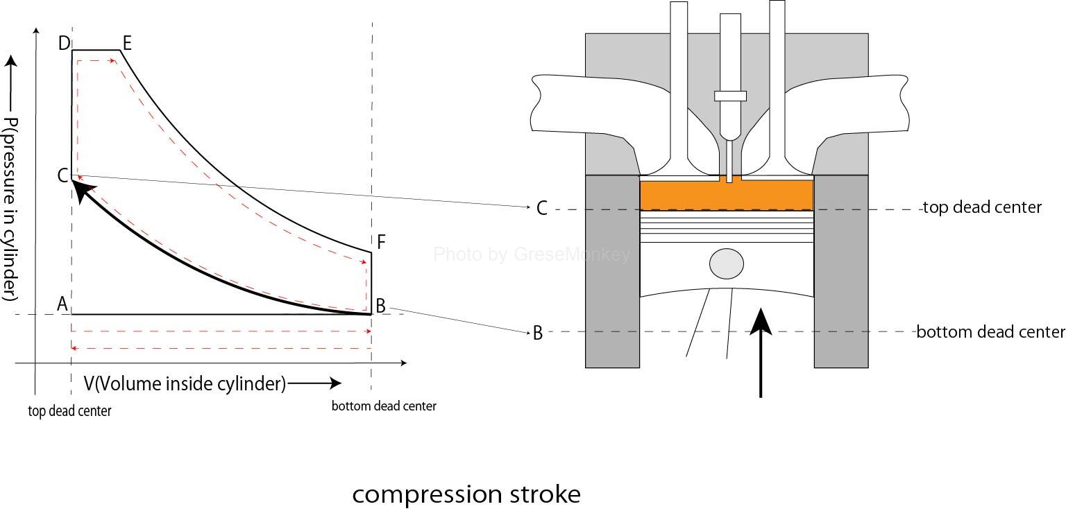
compression stroke
The piston rises from point B, compression begins, the pressure inside the cylinder increases, and the piston rises to point C, where it is located at top dead center.
combustion
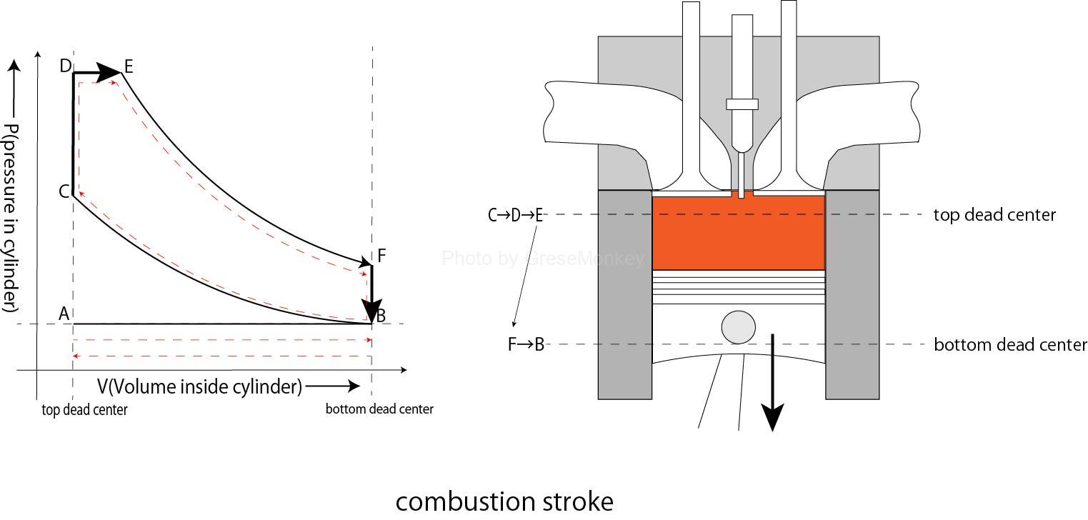
combustion stroke
- Fuel is injected at point C, combustion begins by self-ignition, and the pressure rises rapidly to point D under a constant volume within the combustion chamber.
- After that, even if the piston descends slightly, expansion (combustion) continues under constant pressure up to point E.
- As the piston rises from point B, exhaust begins, and reaches top dead center at point A, completing one cycle.
exhaust
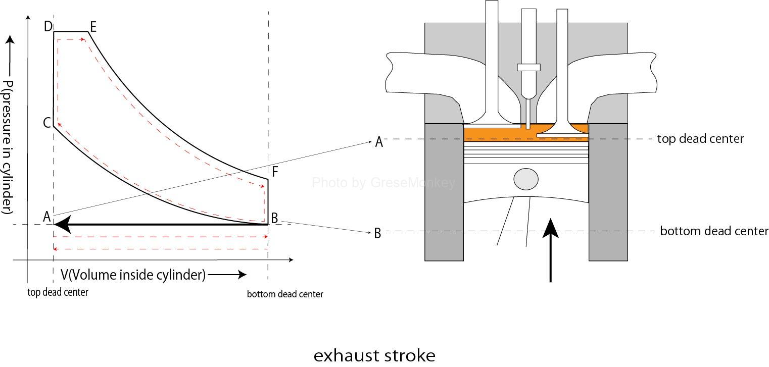
Exhaust process
As the piston rises from point B, exhaust begins, and reaches top dead center at point A, completing one cycle.
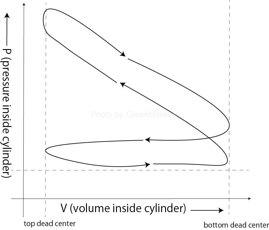
Figure 2: P-V diagram of an actual engine
Figure 1-2 is a P-V diagram of an actual engine, which measures and records the pressure changes of the working gas in the cylinder, and is called a accurate pressure diagram.
The piston and cylinder diagram for one cycle is shown.
valve timing
Valve timing is closely related to how fuel is combusted. Therefore, depending on the valve timing settings, engine output and the generation of harmful exhaust gases can also be affected.
Therefore, it is necessary to set appropriate valve timing in consideration of engine characteristics, usage conditions, etc.
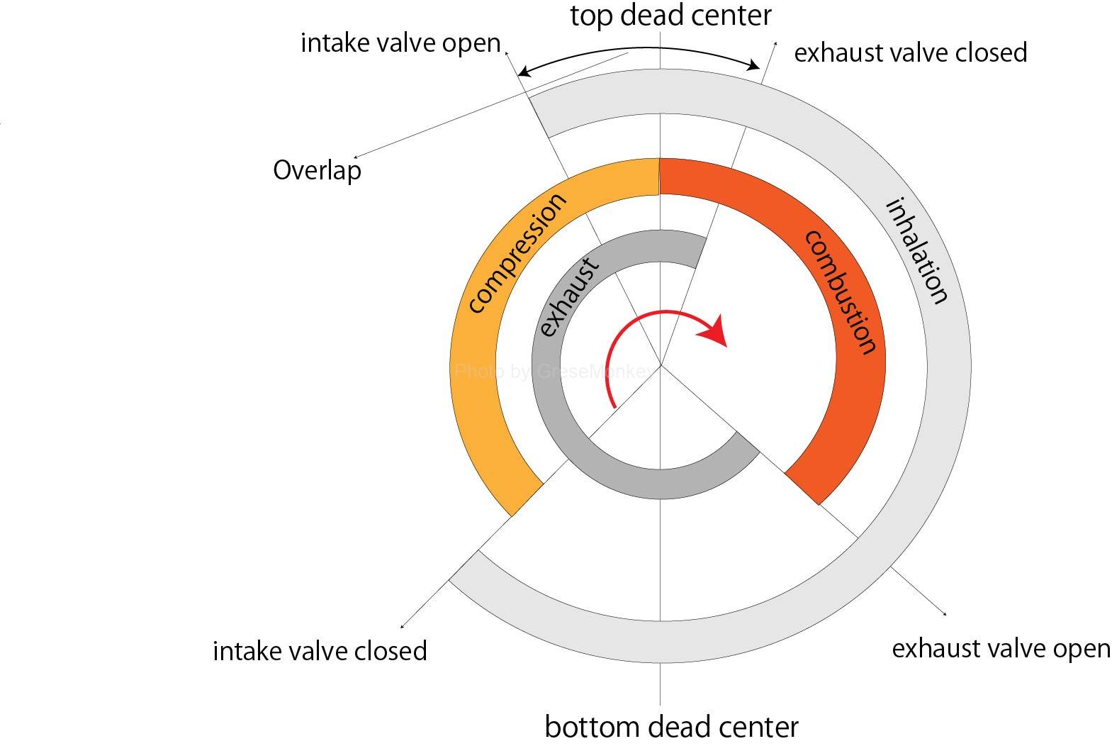
Figure 3: Valve timing diagram
Intake valve opening/closing timing
Considering when the valve starts to open, the moment the valve leaves the valve seat, the ventilation area is extremely small, so if the piston reaches the top dead center position in this state, there will be enough airflow when the piston starts to descend. It becomes impossible to obtain a ventilation area, and the suction resistance only increases and the volumetric efficiency decreases. (Intake air cannot be taken in efficiently.)
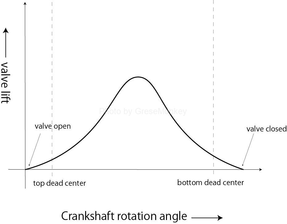
Figure 4: Intake valve opening/closing timing
Therefore, as shown in Figure 1-4, the valve is opened slightly earlier than the piston reaches the top dead center position, and the ventilation area is maximized at the position where the piston begins to descend and the piston speed is the highest. The valve timing is adjusted accordingly. (Intake air can be taken in efficiently.)
In addition, by keeping the valve open for a certain period after bottom dead center as shown in the diagram, the amount of intake air can be increased by utilizing the inertia force when the piston descends during intake. That’s what I do.
Exhaust valve opening/closing timing
The valve opens just before bottom dead center at the end of the combustion stroke, allowing exhaust gases to be discharged using their own pressure.
In addition, the timing at which the valve closes is such that even if the piston reaches top dead center during the exhaust stroke, the pressure inside the cylinder is higher than atmospheric pressure, so by keeping the valve open for a certain period of time after top dead center, Improves exhaust efficiency.
Thermal efficiency
In a heat engine, the ratio between the amount of heat converted into work and the amount of heat from the supplied fuel is called the thermal efficiency of the heat engine. There are different types of thermal efficiency depending on how it is determined:
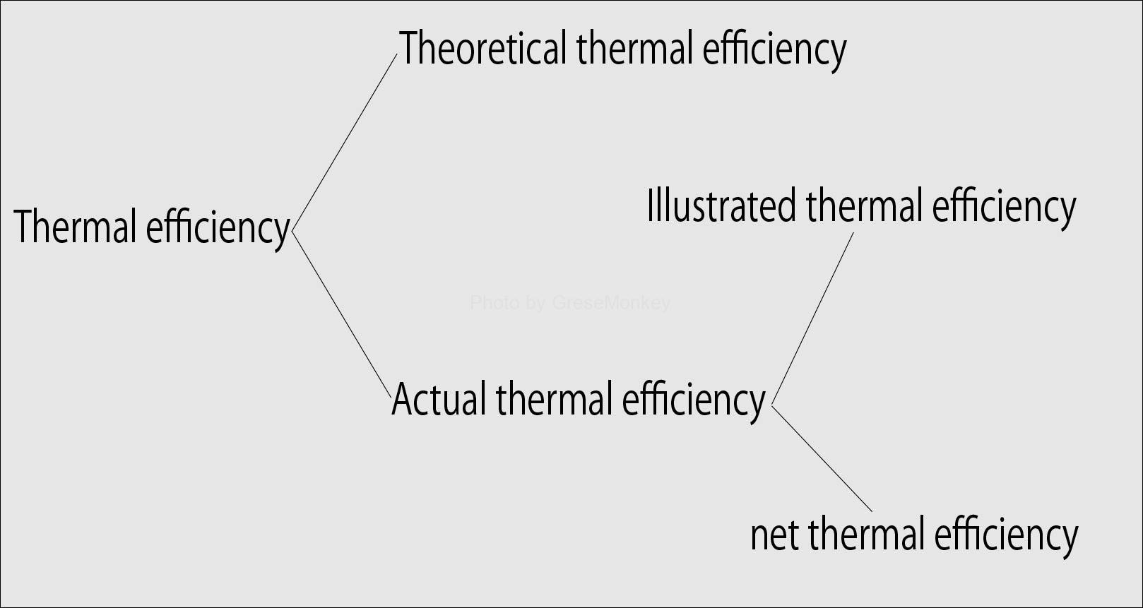
Theoretical thermal efficiency
Theoretical thermal efficiency refers to the ratio between the amount of heat that can be converted into work and the amount of heat that can be supplied in a theoretical cycle.
Illustrated thermal efficiency
Indicated thermal efficiency refers to the ratio between the work done by the working gas in the cylinder to the piston, converted into heat, and the supplied heat.
The work given to the piston by the working gas is called indicated work, and its power is called indicated power.
The indicated work can be determined from the acupressure diagram, but it is smaller than the theoretical work due to cooling loss, work required for intake and exhaust, etc.
Therefore, the indicated thermal efficiency is always less than the theoretical thermal efficiency.
Net thermal efficiency
Generally, the thermal efficiency of an internal combustion engine is called the net thermal efficiency, which is the ratio of the work calculated from the net power converted into heat and the total heat of the fuel used to obtain power.
Note that the work calculated from the net power is calculated by subtracting the friction of moving parts and the work required to move auxiliary devices such as the water pump, fan, and alternator from the indicated work.
In fact, the power obtained from the engine’s crankshaft is called net power or shaft power.
The net thermal efficiency can be expressed as follows.
net thermal efficiency = amount of heat converted into power by the engine / Total heat of fuel given to the engine amount of heat converted into power by the engine
Average effective pressure
Average effective pressure is the work done in one cycle divided by the stroke volume, and is used when comparing the performance of engines with different displacements and operating methods.
There are three types of average effective pressure: theoretical average effective pressure, indicated average effective pressure, and net average effective pressure.
The theoretical average effective pressure is determined by the following formula.
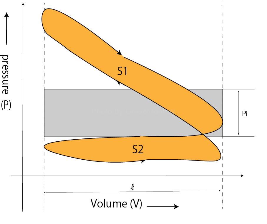
Figure 5: Acupressure diagram
Indicated power and net power
Note that the mechanical efficiency is calculated from the indicated power and the net power using the following formula.
mechanical efficiency = net power / Indicated power ✕ 100(%)
Engine losses
The following losses occur before the calorific value generated by fuel combustion is converted into useful work as shaft output.
heat loss
- cooling loss
- exhaust loss
- radiation loss
mechanical loss
pump loss
Volumetric efficiency and filling efficiency
volumetric efficiency = Volume of newly inhaled air in conditions P and T / Total process volume = Mass of newly inhaled air in conditions P and T / The mass of new air occupying the total stroke volume in conditions P and T
filling efficiency = Mass of newly inhaled air in conditions P and T / Mass of air occupying the total stroke volume in conditions P0 and T0
excess air rate
Sufficient oxygen is required for complete combustion of fuel, but since the amount of oxygen contained in the air is fixed, the amount of fuel used for combustion depends on the mass of air taken in during the engine intake process. The maximum amount of is determined.
For example, the theoretical mass of air required to completely burn 1 kg of diesel oil is approximately 15 kg.
However, since combustion actually occurs in a short period of time, complete combustion cannot be achieved with the theoretically required amount of air, so a larger amount of air is required.
This excess air ratio is called the excess air ratio and is expressed by the following formula.
excess air rate = mass of air actually inhaled / Theoretical air mass for complete combustion of injected fuelIn diesel engines, combustion occurs within a short period of time after fuel is injected into the air, making it difficult to mix the fuel and air sufficiently.
Therefore, the excess air ratio is about 1.2 to 1.4 at full load (maximum injection amount), and is 2.5 or more when the load is low (low injection amount) at low speed.
Engine output test
Engine output test methods for automobiles are standardized by JIS, and include a gross shaft output test methodand anet shaft output test method under full engine load conditions.
- Gross axis output
This is the shaft output measured on an engine test stand with only the accessory equipment necessary for engine operation installed.
- Net shaft output
This is the shaft output measured on an engine test stand with all the accessories necessary to use the engine for a specific purpose.
Note that the net shaft output test method is currently the mainstream.
diesel engine combustion
combustion process
The fuel particles injected into the combustion chamber in the form of a high-pressure mist are heated by the compressed, high-temperature air, their temperature drops, they begin to vaporize, and when they mix with the high-temperature air, they self-ignite and burn.
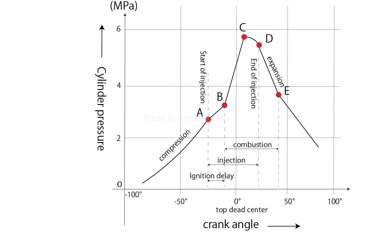
Figure 6: Combustion status of diesel engine
The relationship between the change in pressure inside the cylinder due to combustion and the rotation angle of the crankshaft (crank angle) is shown in Figure 6, and the combustion process changes as follows.
Ignition delay period (combustion preparation period: A-B)
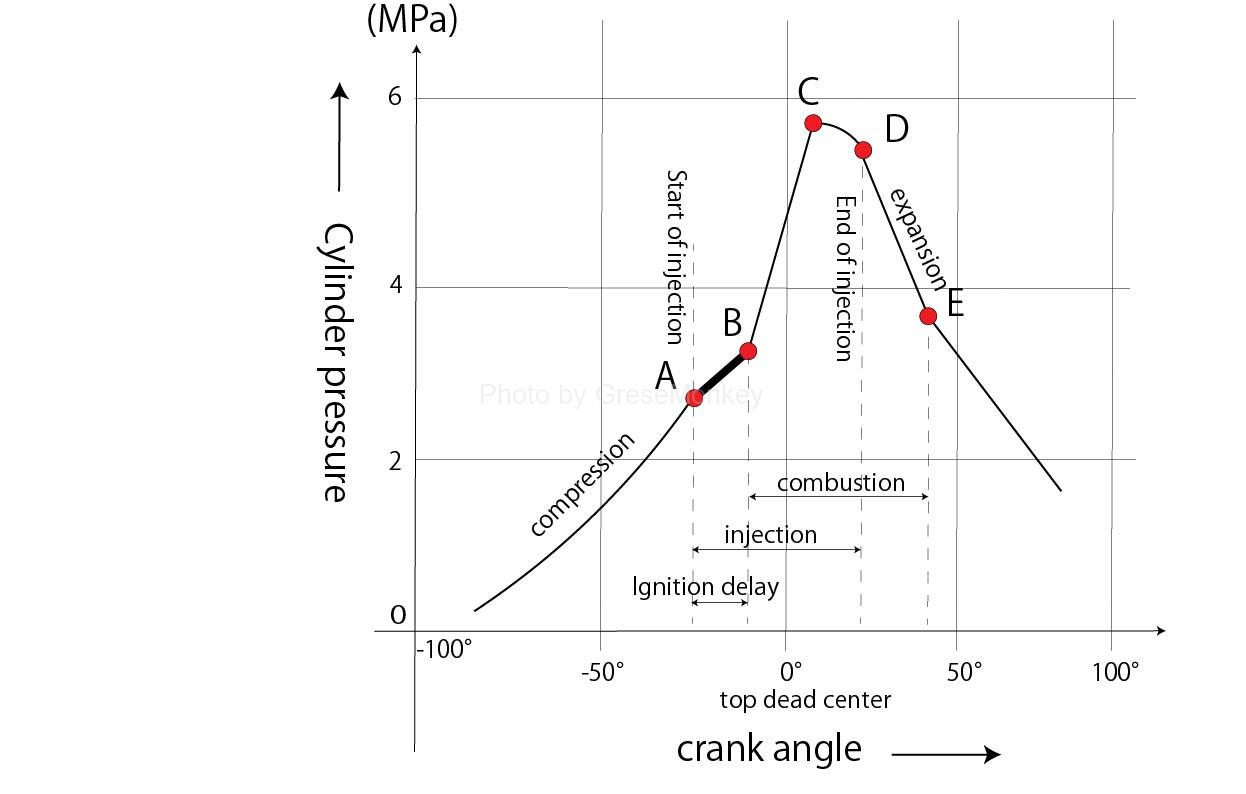
Figure 6-1: Diesel engine combustion status between A and B
The period from A to B in Figure 6-1 is the ignition delay period, and at A, fuel is injected in the form of a high-pressure mist, and is heated by the compressed and high-temperature air in the cylinder to form an air-fuel mixture.
A-B is the period when the ignition temperature is approaching.
Also, A-B is a short period of time, and the pressure does not rise rapidly.
Flame propagation period (constant volume combustion period: B-C)
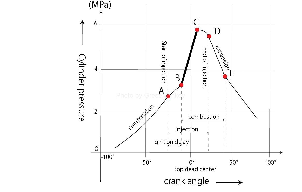
Figure 6-2: Diesel engine combustion status between B and C
B-C in the diagram is the flame propagation period, and preparations for combustion are made during the ignition delay period.
When ignition occurs at one or several locations in the air-fuel mixture at B in the diagram, it propagates extremely rapidly to each location, combusts almost simultaneously, and the pressure rises rapidly.
The pressure increase at this time is related to the amount of fuel injected during the ignition delay period, the atomization state, etc., and in state C at the end of this period, most of the injected fuel is burned out.
Direct combustion engine (constant pressure combustion engine: C-D)
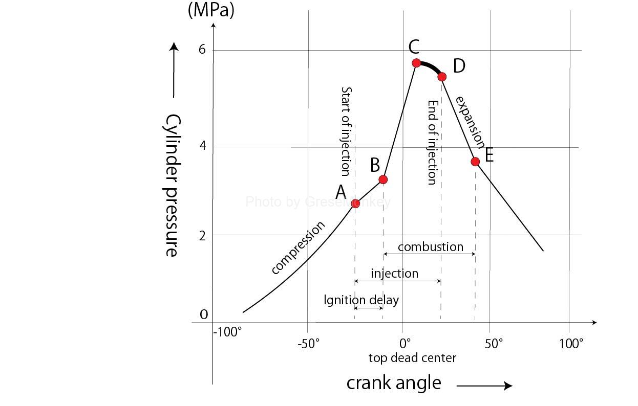
Figure 6-3: Diesel engine combustion status between C and D
The engine from C to D in the diagram is a direct combustion engine, and even after C, fuel is still injected, but the flame generated between B and C causes the injected fuel to burn.
Late combustion period (afterburn period: D-E)
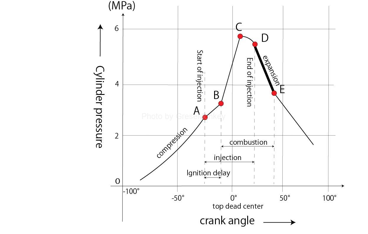
Figure 6-4: Diesel engine combustion status between D and E
The engine from D to E in the diagram is a direct combustion engine. At D, injection ends and the combustion gas expands, but any fuel that has not been completely combusted up to that point is combusted during the expansion period.
In this way, combustion can be considered to be divided into four engines, but the ignition delay period and flame propagation period are also considered to be preparation periods for a direct combustion engine, and the conditions during this period have a large effect on combustion. It will have an impact.
diesel knock
As described above, diesel knock causes a time delay until the fuel injected into the combustion chamber forms a combustible mixture and self-ignites.
After the fuel injected during this ignition delay period self-ignites, it rapidly burns and the pressure increases, resulting in louder combustion noise than in a gasoline engine.
Diesel knock is a condition in which the combustion pressure and pressure rise rate after self-ignition become abnormally high, generating shock waves and causing a high-pitched knocking sound that violently vibrates mechanical parts. This tends to occur when the amount of fuel is higher than the specified value, or when self-ignition is delayed due to cold starting.
In order to prevent diesel knock, the amount of injection during the ignition delay period is closely related to the cause of its occurrence.
Therefore, measures have been taken to reduce the amount of injection at the beginning of injection and to install a preheating device to facilitate self-ignition during cold conditions.Other methods include the following. Conceivable.
- Use fuel with good ignitability (high cetane number)
- Increasing the temperature inside the cylinder (increasing the compression pressure)
- Keeping the cooling water at an appropriate temperature
- Appropriate injection timing
- Appropriate fuel injection pressure and spray condition
exhaust gas
Exhaust gas generation process
After the mixture is combusted, most of the exhaust gas becomes N2 (nitrogen), H2O (water, water vapor), and CO2 (carbon dioxide), but in addition, monoxide, which is harmful and causes air pollution, is (carbon), HC (hydrocarbons), NOx (nitrogen oxides), PM (particulate matter), etc.
- CO
2C(carbon) + O2(oxygen) → 2CO

    However, if there is sufficient air supply and combustion occurs completely, CO2 will be produced as shown below.

C + O2 → CO2
Diesel engines have a large excess air ratio, and combustion occurs with a sufficient supply of air, so CO emissions are extremely low.
- HC
HC is a general term for a compound of hydrogen and carbon. When completely combusted, C becomes CO2 as mentioned above, and H2 (hydrogen) becomes H2O as shown below.
2H2 + O2 → 2H2OHC discharged from the exhaust pipe is the unburned gas that is emitted as is from incomplete combustion of fuel.
In diesel engines, combustion occurs in sufficient air, so HC is generated less.
- NOx
NOx is a general term for compounds of nitrogen and oxygen.
It occurs when the combustion gas temperature is high, and there are various types depending on the degree of combination with oxygen (oxidation).
In the presence of N2 and O2 at high temperatures

    N2 + O2 → 2NO

    This reaction occurs and NO (carbon monoxide) is generated, but when NO comes into contact with O2 in the air,

    2NO + O2 → 2NO2

    This reaction occurs and it changes to NO2 (nitrogen dioxide).

    In other words, NOx in exhaust gas is mainly NO and NO2.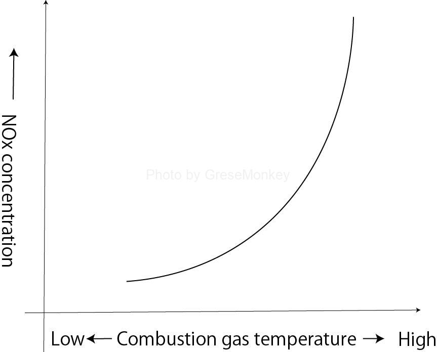
Figure 7: Combustion gas temperature and NOx concentration
As shown in Figure 7, NOx increases rapidly as the temperature of the combustion gas increases.
While CO and HC are generated due to incomplete combustion, NOx, on the other hand, is generated in large quantities when combustion occurs completely and the combustion gas temperature is high.
Therefore, in order to prevent the generation of NOx, it is necessary to lower the maximum combustion gas temperature, but doing so will have negative effects such as a reduction in engine output.
- PM
PM is broadly classified into three types: black smoke, sulfate, and SOF (Soluble Organic Fraction).
Black smoke is the carbon in the fuel that separates and is emitted as soot.
Diesel engines have a sufficient amount of intake air, but during sudden acceleration, which requires a large amount of injection, or under high load, partially vaporized fuel particles may be exposed to the high-temperature combustion flame. The carbon in the fuel separates and is emitted as black smoke.
Sulfate is a general term for sulfur compounds produced by the participation of sulfur in fuel, and is produced in large amounts when the engine is under high load or when a catalyst with strong oxidizing power is present.
SOF is an organic component with a relatively low boiling point that can be extracted with a solvent. Specifically, SOF is the unburned part of light oil used as a fuel or oil mixed into the combustion chamber.
Countermeasures for exhaust gas purification
How to reduce NOx and PM, which are the main components of diesel engine exhaust gas
NOx reduction
- Multistage fuel injection
Common rail high-pressure fuel injection systems reduce NOx emissions by injecting a small amount of fuel before main injection.
- EGR device (exhaust gas recirculation)
By recirculating a portion of the exhaust gas to the intake manifold, the oxygen concentration in the intake air is reduced, which lowers the maximum combustion gas temperature and reduces NOx emissions.
PM reduction
- Improvement of engine body
By increasing the number of valves and improving the shape of the combustion chamber, we aim to improve combustion efficiency and reduce PM generation by optimizing the mixture of fuel and air.
- Higher fuel injection pressure
In common rail type high pressure fuel injection systems and unit injector type high pressure fuel injection systems, the fuel is atomized by increasing the fuel injection pressure, and the fuel is brought into contact with the surrounding air and heat, resulting in good combustion conditions and significantly reducing the generation of PM. reduced to