Electronic control device / automobile sensor
- Electronic control device
As shown in Fig. 1, the electronic control unit centrally controls the engine electrical components such as ignition timing control, idle rotation speed control (ISCV), and throttle valve opening control, centering on fuel injection control. The engine is operated in the optimum state according to the situation.
The electronic control device is composed of a sensor that detects the operating state of the vehicle and the engine, a control unit that performs calculations based on the signal information thereof, and an actuator that operates by a signal as a result of the calculation from the control unit.
In addition, it is equipped with a self-diagnosis system that notifies the abnormal system when an abnormality occurs in the signal system from the angle sensor, and a fail-safe function and a backup function for avoiding danger.
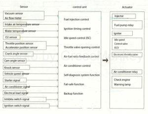
Figure 1: Electronic control system diagram
- Structure / function of automobile sensor
Sensors installed in automobiles detect electrical signals according to the operating conditions of the vehicle and engine and input them to the control unit.
Here, a basic example of a vacuum sensor, an air flow meter, a throttle position sensor, an accelerator position sensor, an O2 sensor, a crank angle sensor, and a cam angle sensor will be described.
Intake air volume measurement
Vacuum sensor
The vacuum sensor is a semiconductor sensor that utilizes the property of changing its electrical resistance (piezoresistive effect) when stress is applied to silicon (semiconductor crystal), and inputs the inlet manifold pressure as an electrical signal to the control unit.
In the control unit, the intake air amount is calculated from this electric signal and used for controlling the fuel injection amount, ignition timing, ISCV, and the like.
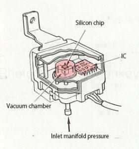
Figure 2: Vacuum sensor
As shown in Fig. 2 and Fig. 3, the vacuum sensor has a silicon chip in which a bridge circuit is formed by four variable resistors mounted in a sensor unit kept in vacuum, and inlet manifold pressure acts on one side of the silicon chip. It has a structure.
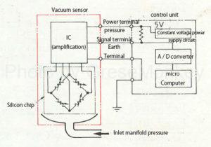
Figure 3: Vacuum sensor circuit diagram
When pressure is applied to the sensor, the silicon chip receives the stress generated by the pressure difference from the vacuum chamber on the opposite side, and the four variable resistance values change.
The potential difference due to this resistance change is amplified by the IC, converted into an electric signal, and input to the control unit.
The control unit that receives the electric signal is converted into a digital signal by the built-in A / D converter, and is calculated by the arithmetic unit (microcomputer / CPU) according to each condition.
The output voltage of the vacuum sensor has a characteristic that the output voltage increases almost proportionally as the inlet manifold pressure increases.
For example, the atmospheric pressure changes depending on the weather, but the vacuum sensor detects the difference from the vacuum state, that is, the absolute pressure, so it is always appropriate without being affected by the atmospheric pressure around the vehicle. It is possible to detect the electric signal of the inlet manifold pressure.
Air flow meter
The air flow meter is installed between the air cleaner and the intake pipe, detects the intake air amount of the engine as an electric signal, and inputs it to the control unit. The intake air amount is calculated from this electric signal and used to control the fuel injection amount, ignition timing, ISCV, etc.
The types of air flow meters include a heat ray type, a Karman vortex type, and a measuring plate type. Here, the heat ray type will be described.
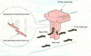
Figure 4: Hot wire air flow meter
The heat ray type air flow meter is provided in the middle of the intake passage as shown in FIG. 4, and is composed of a heat generating resistor (heat ray) and a (temperature compensation resistor) that operate at a constant temperature of several hundred degrees.
The electric signal detection of the intake air amount is performed by the bypass flow of the intake air cooling the heating resistor as shown in FIG.
The principle utilizes the property that the temperature applied to the heating resistor changes (cools) and the resistance value changes at the same time depending on the influence of the amount of intake air, and as a result, the current flowing in the path of the heating resistor. It applies that it fluctuates. (Electrical circuit: Ohm’s law)
The electric resistance value of the heating resistor is small when the temperature is low, and the resistance value is large when the temperature is high.
Therefore,
- When the amount of intake air is small, the amount of heat radiated from the heat generating resistor is small and the electric resistance value is large, so that the current flowing through the circuit is small.
vice versa
- When the amount of intake air is large, the amount of heat radiated from the heat generating resistor is large and the electrical resistance is small, so that the current in the circuit increases.
The control unit replaces the change in the current due to this electric signal with the change in the voltage and detects it as the intake air amount.
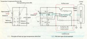
Figure 5: Heat-wire air flow meter circuit
The actual circuit is as shown in Fig. 5, and when the amount of intake air increases, the heat of the heating resistor is taken away, so the current must be increased to keep the temperature of the heating resistor constant.
Therefore, a resistor (Rk / Rb) is provided in parallel with the circuit of the heat-generating resistor shown in Fig. 5 (2), and the current is controlled by a comparator so that the voltages of Va and Vb are equal. doing.
For this change in current value, the voltage of Va in Fig. 5 (2) is detected, and the current value of I = Va / Ra (Ohm’s law) is obtained by the control unit (microcomputer / CPU).
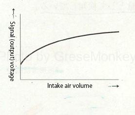
Figure 6: Output characteristics
Since the voltage Va changes with the current I, the signal voltage rises as the intake air amount increases and decreases as the intake air amount decreases, as shown in the characteristics of FIG.
Further, when the air flow rate is measured only by the heat generating resistor (Rh) shown in FIG. 5 (2), even if the intake air amount is the same, the amount of heat taken from the heat generating resistor (Rh) differs depending on the air temperature. It becomes impossible to measure the amount of air accurately. (What you want to measure is the amount of air, not the temperature of the air.)
Therefore, in order to improve this, a temperature compensation resistor (Rk) is installed in the bypass passage to measure the temperature of the intake air.
Since the resistance value of Rk is set to be larger than that of Rh, the current flowing through the circuit is small and the heat generated by the resistor itself is small, so that there is almost no influence of the temperature change due to the air flow rate unlike the heat-generating resistor.
For example, even if the amount of intake air is the same, the resistance values of Rh and Rk increase as the intake air temperature increases.
Even if the amount of air (volume amount) is the same, the higher the temperature of the air, the smaller the current I, so the voltage of Va becomes smaller. This makes it possible to detect the intake air mass.
Throttle valve opening / accelerator depression amount detection
Throttle position sensor
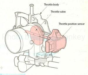
Figure 7: Throttle body
As shown in Fig. 7, the throttle position sensor is attached to the throttle valve of the throttle body at the same time as the complaint, and outputs the opening degree of the throttle valve as an electric signal, and the control unit outputs this signal as the fuel injection amount and ignition. It is used to control the timing and ISCV.
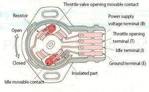
Figure 8: Throttle position sensor
The throttle position sensor shown in FIG. 8 detects the throttle opening position by moving the opening movable contact with the throttle valve on the resistor. Explaining in the circuit diagram of FIG. 9, the resistor inside the sensor ( A constant voltage is applied from the control unit to both ends of r), and the voltage of the control unit T terminal changes as the movable contact moves on the resistor (r) according to the opening degree of the throttle valve. This signal is digitally converted by an A / D converter and input to a microcomputer.
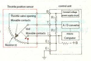
Figure 9: Throttle position sensor circuit diagram
The T terminal is connected to the constant voltage power supply circuit via a resistor (R1) inside the control unit and to the E2 terminal via a resistor (R2), but the resistance values of R1 and R2 are much higher than those of r. Since it is large, the current flows from the B terminal to the r to the E2 terminal, and the voltage at the T terminal is hardly affected by R1 and R2.
A constant voltage is applied to the I terminal, but when the throttle valve is fully closed, the idle movable contact turns ON and the voltage of the I terminal becomes 0V. The microcomputer of the control unit determines the opening degree of the throttle valve from the input signals from these T terminals and I terminals.
Accelerator position sensor
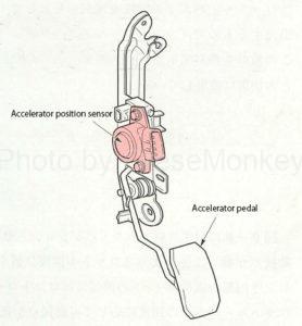
Figure 10: Accelerator position sensor mounting position
The accelerator position sensor is mainly used in an electronically controlled throttle device, and is attached near the accelerator pedal as shown in FIG.
By moving the accelerator pedal opening movable contact on the resistor in the sensor, the signal of the accelerator pedal depression amount and depression speed is input to the control unit.
The control unit uses this signal for fuel injection control, ignition timing control, ISCV, and so on.
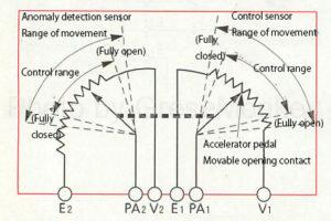
Figure 11: Accelerator position sensor
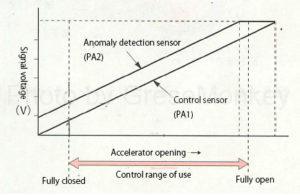
Figure 12: Output characteristics of the accelerator position sensor
The accelerator position sensor is provided with two sensors, one for control and one for abnormality detection, as shown in Fig. 11, and keeps a constant difference until the specified voltage is reached as shown in Fig. 12. ..
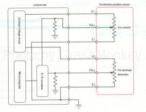
Figure 13: Accelerator position sensor circuit
The circuit of the accelerator position sensor is as shown in Fig. 13, and the control unit monitors the difference in the output voltage of each sensor, and when the difference occurs, it judges that it is abnormal and outputs a diagnostic code. Then, fail-safe is executed so that the vehicle can evacuate.
Air-fuel ratio detection
O2 sensor
The O2 sensor detects the oxygen concentration in the exhaust gas and outputs it as an electric signal, and the control unit uses this signal to control the fuel injection amount and ignition timing. Here, the electromotive force amplification action of the zirconia type O2 sensor will be described.
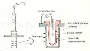
Figure 14: O2 sensor (zirconia type)
As shown in Fig. 14, the zirconia type O2 sensor is a test emotion zirconia element coated with platinum that amplifies the electromotive force. The atmosphere is introduced on the inner surface, and the outer surface is exposed to high-temperature exhaust gas. Is done.
Zirconia elements have the property of generating electromotive force when the difference in oxygen concentration between the inner and outer surfaces is large at high temperatures.
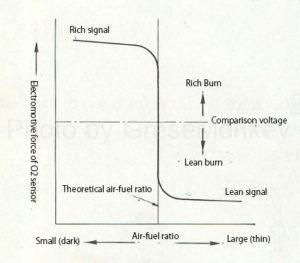
Figure 15: Output characteristics of O2 sensor
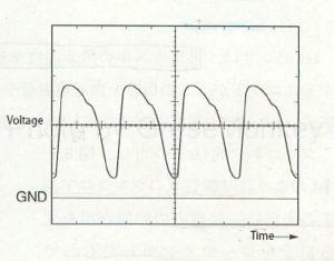
Figure 16: Voltage characteristics of O2 sensor
Since this electromotive force changes suddenly near the stoichiometric air-fuel ratio, the control unit installs a comparison voltage near the middle of the voltage fluctuation as shown in Fig. 15, and when the output of the O2 sensor is higher than the comparison voltage, the theory It is determined that the fuel is richer than the air-fuel ratio, and conversely, when the output of the O2 sensor is lower than the comparison voltage, it is determined that the fuel is thin, and the fuel injection amount of the injector is controlled.
That is, when it is determined that the fuel is rich, the injection amount is gradually reduced, and when it is determined that the fuel is thin, the fuel is gradually increased again.
Therefore, the output voltage characteristic of the O2 sensor has a periodic waveform as shown in FIG.
In addition, the coated platinum has a catalytic action of binding oxygen and CO in the exhaust gas, lowers the oxygen concentration near the zirconia element on the exhaust gas side, and increases the oxygen concentration difference from the atmosphere side. This makes it easier to generate the electromotive force of the sensor.
In other words, even if a mixture that is slightly richer than the stoichiometric air-fuel ratio burns, a small amount of oxygen remains in the exhaust gas, so the catalytic action of platinum is used to react the remaining oxygen with CO to reduce the amount of oxygen. The sensitivity of the sensor is increased by making it.
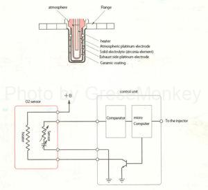
Figure 17: O2 sensor (with heater) circuit
Many O2 sensors have a heater built in as shown in Fig. 17 in order to keep the temperature of the zirconia element constant even when the load is light and to output stable power. The current flowing through the heater is controlled.
Engine speed and piston reference position detection
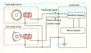
Figure 18: Crank angle sensor / cam angle sensor circuit diagram
An electromagnetic pickup sensor is used for the crank angle sensor and the cam angle sensor, and signals for detecting the crankshaft angle, rotation speed, and piston reference position are output to the control unit as shown in FIG. 18, and these signals are output. It is used to control the fuel injection timing, ignition timing, etc. based on.
Principle of signal generation
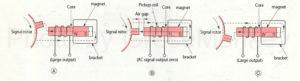
Figure 19: Principle of AC signal generation
In FIG. 19, the magnetic flux from the magnet passes through the path of magnet → pickup coil → signal rotor → bracket → magnet, but when the signal rotor is not rotating, the magnetic flux does not change, so there is no change in the pickup coil. Does not happen either.
However, when the signal rotor rotates, the air gap between the signal rotor protrusion and the pickup coil changes as shown in FIGS. 19 (A), (B), and (C), so the magnetic flux passing through the pickup coil changes, and this magnetic flux changes. A voltage corresponding to the amount of change is generated across the pickup coil.
Since this generated voltage is generated in a direction that hinders the change in magnetic flux, when the signal rotor protrusion approaches the center of the pickup coil (when the air gap becomes smaller and the speed increases … Fig. 19 (A)). , When separated (when the air gap becomes large and the magnetic flux decreases … Fig. 19 (C)), the direction is opposite, so it appears as an AC signal.
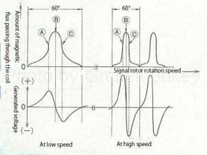
Figure 19: Principle of AC signal generation
Further, this generated voltage is higher as the amount of change in magnetic flux is larger and the change time is shorter. Therefore, when the protrusion of the signal rotor faces the center of the pickup coil (FIG. 19 (B)), the amount of magnetic flux is increased. At the maximum, the amount of change is zero, so the generated voltage is also zero, but before and after that (Fig. 19 (a) (c)), the generated voltage is maximum, and the maximum value increases as the engine speed increases. growing.
Cam angle sensor
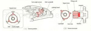
Figure 20: Cam angle sensor
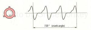
Figure 21: Output waveform of the cam angle sensor
The cam angle sensor is attached to the cylinder head, detects the crank angle reference position (top dead center and cylinder discrimination), which is the basic signal for sending an appropriate ignition signal to the igniter, and controls the electric signal. I am sending it to.
Crank angle sensor
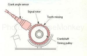
Figure 22: Crank angle sensor mounting position
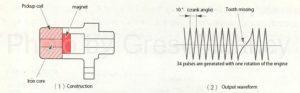
Figure 23: Example of crank angle sensor structure and output waveform
Fig. 22 and Fig. 23 (1) are examples of the crank angle sensor, which are installed near the crankshaft timing pulley. The timing rotor is integrated with the timing pulley and has 34 teeth with 2 missing teeth.
Therefore, when the crankshaft makes one rotation, 34 signals are generated as shown in the output waveform of FIG. 23 (2). By outputting this signal to the control unit, the crank angle can be detected every 10 °.
Further, by detecting the signal of the missing tooth portion, the accurate top dead center can be known.
In other words, assuming that the center is attached so that the missing tooth part of the timing rotor matches the alignment mark of the timing crank pulley, for example, the first cylinder will move in the same way as when replacing the timing belt. If the alignment mark is aligned so as to be the compression top dead center, the signal of the automatically missing tooth can also indicate the compression top dead center of the first cylinder.
Based on this, when synchronizing the cam angle sensor and the crank angle sensor, the top dead center position of each cylinder is set from the engine rotation angle from this missing tooth as a reference position (mark). The signal waveform can be set.
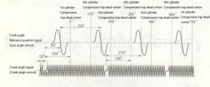
Figure 24: An example of a crank angle signal waveform
FIG. 24 is an example of tuning the signal waveforms of the crank angle sensor and the cam angle sensor. The figure shows a 6-cylinder engine, and the position 150 ° from the center of the missing tooth is the first cylinder and the first cylinder. It becomes the compression top dead center of 6 cylinders. Further, the position rotated by 120 ° from those positions is the compression top dead center of the 5th cylinder and the 2nd cylinder, and the position rotated by 120 ° is the compression top dead center of the 3rd cylinder and the 4th cylinder.
Temperature detection
Water temperature sensor / intake sound sensor
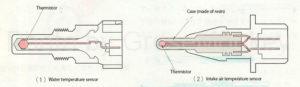
Figure 25: Water temperature sensor and intake sound sensor
Both the water temperature sensor and the intake sound sensor are sensors for measuring temperature, and a thermistor with the same characteristics is incorporated inside the tip as shown in FIG. 25.
These sensors are connected as shown in the circuit of FIG. 26, in which the thermistor replaces the change in temperature with the change in resistance value so that the microcomputer in the control unit can detect the change in voltage value. It is intended to be replaced with change.
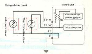
Figure 26: Water temperature sensor and intake sound sensor circuit
In the water temperature sensor circuit, the THW (water temperature signal) voltage in the figure, that is, the voltage obtained by dividing the 5V voltage from the constant voltage circuit by the resistance R2 and the resistance of the water temperature sensor is detected by the microcomputer.
In the intake sound sensor circuit, the THA (intake air temperature signal) voltage shown in the figure is detected by the microcomputer according to the voltage division between R1 and the thermistor resistance, similar to the water temperature sensor circuit.
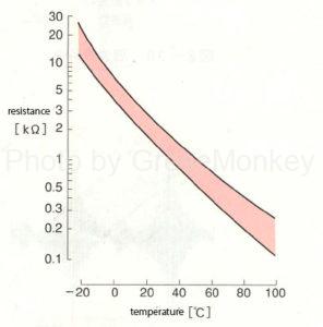
Figure 27: Thermistor temperature and resistance characteristics
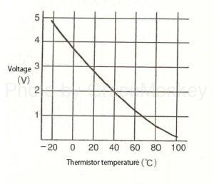
Figure 28: Relationship between THA and THW voltages and thermistor temperature
These THA and THW voltages rise as shown in FIG. 28 because the resistance value increases as the temperature of the thermistor decreases, as shown in FIG. 27.
Therefore, the microcomputer of the control unit detects the temperature by these voltages.
The control unit uses the voltage signal of the water temperature sensor THW for fuel injection amount control, ignition timing control, ISCV, etc., and the voltage signal of the intake sound sensor THA for fuel injection amount control.
* THW = Thermo Water THA = Thermo Air
Other signal detection
Knock sensor
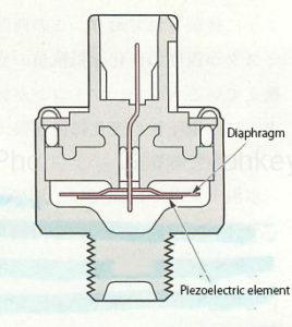
Figure 29: Knock sensor
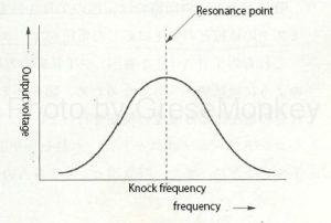
Figure 30: Frequency characteristics
Inside the knock sensor, a piezoelectric element is assembled on a diaphragm that resonates at the knocking frequency. When knocking occurs, the diaphragm resonates and a large voltage is generated from the piezoelectric element at the resonance point as shown in FIG. As shown in Fig. 31, the voltage at this resonance point is converted into a digital signal by an A / D converter and input to the microcomputer to control the ignition timing.
FIG. 32 shows the output voltage waveform of the knock sensor by the oscilloscope.
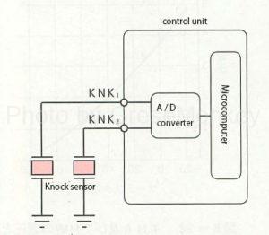
Figure 31: Knock sensor circuit
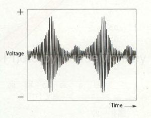
Figure 32: Output voltage waveform
* Piezoelectric element: An electromotive force is generated when pressure or strain is applied. On the contrary, it is a special element that causes distortion when a voltage is applied.
Starter signal
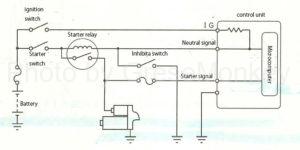
Figure 33: Starter signal and neutral signal circuits
In order to improve the startability of the engine, it is necessary to increase the fuel injection amount at the time of starting to enrich the mixer.
For that purpose, as shown in the circuit of FIG. 33, the voltage applied to the magnet switch of the starter is input to the control unit as a starter signal to correct the injection amount at the time of starting the engine.
Neutral signal
Figure 33: Starter signal and neutral signal circuits
The neutral signal circuit is as shown in Fig. 33. In AT vehicles, it detects whether the shift position is in the P, N range or other than that (L, 2, D, R), and the inhibitor switch is L. , 2, D, R are turned off, and the signal of this switch is input to the control unit and used for ISCV correction when the shift position is switched from the N range to the D range. (Drop correction)
Brake signal
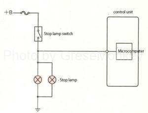
Figure 34: Brake signal circuit
The brake signal circuit is as shown in FIG. 34, which detects the braking state of the vehicle and uses this signal for fuel injection control and ISCV control.
At the time of deceleration, fuel cut control is performed to stop fuel injection in order to aspire to the catalyst and improve fuel efficiency.
The fuel cut rotation speed and the return rotation speed are determined according to the respective vehicle and engine control characteristics, and are changed according to the running state of the vehicle.
Air conditioner signal
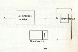
Figure 35: Air conditioner signal circuit
The circuit of the air conditioner signal is as shown in Fig. 35. It detects whether the air conditioner is ON or OFF, and inputs the voltage applied to the magnet switch of the compressor of the air conditioner circuit to the control unit as a signal.
This signal is used to correct the ISCV when the air conditioner is on.
Battery voltage signal
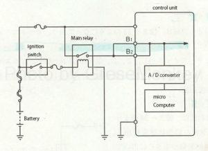
Figure 36: Control unit power supply circuit
The power supply for operating the control unit itself is supplied via a relay as shown in FIG. 36, and the microcomputer in the control unit has a function of detecting the level of the power supply voltage.
The detection result is used to correct the fuel injection time.