Actuator drive control in fuel injection system
The drive control of the actuator is performed by the output signal of the control unit. Here, the fuel injection device will be described.
Fuel injection device
The fuel injection device calculates the injection amount and injection timing so that the control unit has an appropriate air-fuel ratio, and sends the signal from the angle sensor as shown in Fig. 1 to the injector at the appropriate time and for the appropriate time. It is a system that injects fuel by sending a signal.
Here, control by the injector drive circuit and the control unit will be described.
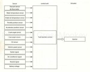
Figure 1: System diagram of fuel injection system
Injector drive circuit
Voltage control type
Fig. 2 (1) shows a voltage-controlled injector drive circuit, and the fuel injection amount is controlled by the length of the energization time of the injector.
The injectors are connected to the control unit as shown in the figure, and in the case of all-cylinder injection as shown in FIG. 1 (1), the injectors of all cylinders are connected in parallel.
In the case of 2-group injection as shown in Fig. 2 (2), 1 ・ 3 ・ 5 and 2 ・ 4 ・ 6 are divided into two groups and connected in parallel. In addition, there are those in which two cylinders are connected in parallel and those in which each cylinder is connected independently.
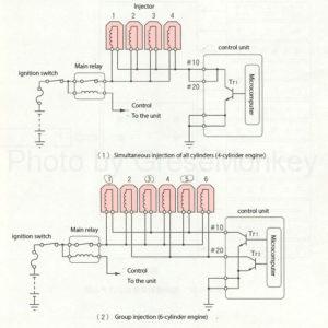
Figure 2: Drive circuit of voltage-controlled injector
The voltage from the battery in the figure is applied from the ignition switch to the main relay, injector, and control unit in both figures 2 (1) and (2).
In Fig. 2 (1), the power transistor is turned on by the output signal from the injection circuit of the injector by the injection signal from the microcomputer, and the injectors 1 to 4 are driven to inject fuel at the same time for all cylinders.
In Fig. 2 (2), when the output signal from the injector drive circuit turns Tr1, the injectors 1, 3, and 5 are driven, and when the output signal turns Tr2 ON, 2. The injectors 4 and 6 are driven to inject fuel in two steps.
- High resistance injector
In the injector used in the voltage-controlled drive circuit shown in Fig. 2, a lead wire with a large resistance is used for the solenoid coil. The reason is that there is a method to improve the responsiveness of the injector by reducing the number of coil turns and increasing the wire diameter, but with this method, the resistance value of the injector becomes small and the current flows too much. There is a drawback that the amount of heat generated increases and the life is shortened.
Therefore, in order to enhance the practicality of the injector, on the contrary, a wire having a large resistance is used, the current is reduced to prevent heat generation, and the life is maintained for a long time.
Such an injector is called a high resistance type injector.
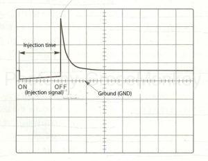
Figure 3: Injection waveform of voltage-controlled injector (measured on the minus side of the injector)
Figure 3 shows the injection waveform (drive waveform) of a voltage-controlled injector using an oscilloscope. When the injection signal is turned on, current starts to flow and the injector is driven, but by the time it is completely driven. , It takes a little time. During this period, fuel is not injected, and this time is called the invalid injection time (invalid drive time).
Current control type
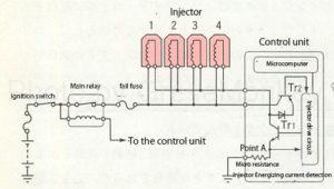
Figure 4: Current-controlled injector drive circuit (simultaneous injection of all cylinders in a 4-cylinder engine)
FIG. 4 shows the drive circuit of the current control type injector, and like the voltage control type described above, the energization time of the injector is controlled by turning ON / OFF of the transistor (Tr1) in the control unit.
The voltage from the battery is applied from the ignition switch to the main relay, fail fuse, injector, and control unit. The injection signal from the microcomputer in the control unit passes through the drive circuit of the injector, Tr1 is turned ON, and injectors 1 to 4 are driven to inject fuel at the same time for all cylinders.
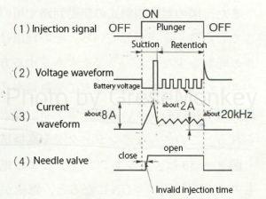
Figure 5: Relationship between each waveform of the current-controlled injector and the needle valve
FIG. 5 shows that the injection signal, the voltage waveform, the current waveform, and the needle valve operations are synchronized when the injector is driven to inject. Figure 5 (1) shows the voltage waveform of the injection signal when OFF → ON → OFF from the microcomputer in the control unit.
Figures 5 (2) and 5 (3) show the waveforms of the voltage and current applied to the injector coil.
When Tr1 is turned on by the output signal from the injector drive circuit in Fig. 4 and current starts to flow in the coil, the voltage starts to drop as shown in Fig. 5 (2) and at the same time as shown in Fig. 5 (3). When the current increases and reaches the specified voltage value (the injector energizing current at point A in the control unit in Fig. 4 is actually detected by replacing it with the voltage) from the injector drive circuit in Fig. 4. Output signal stops and Tr1 is turned off. This corresponds to the period of suction of the plunger of the injector, and the injection response of the injector is improved by shortening the invalid injection time of the needle valve in FIG. 5 (4) as much as possible.
When the current applied to the injector coil described above decreases and drops below the specified voltage, Tr1 turns ON again. The ON / OFF operation of Tr1 is repeated at a frequency of about 20 kHz in the waveform of Fig. 5 (2), which corresponds to the period of holding the plunger of the injector, and the heat generation of the injector coil is suppressed by the small current. ..
In addition, Tr2 shown in Fig. 4 absorbs the counter electromotive force from the injector coil when Tr1 is turned on and off to the extent shown in Fig. 5 (2), thereby suppressing a sudden decrease in the energizing current and controlling it. It’s easy.
The fail fuse blows when an excessive current flows through the injector for some reason, and cuts off the energization of the injector to protect it.
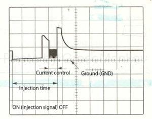
Figure 6: Current-controlled injector injection waveform (measured on the minus side of the injector)
Figure 6 shows the injection waveform of a current-controlled injector using an oscilloscope.
The difference from the voltage control type is that the back electromotive force is smaller than that of the current control part. Further, when the injection amount increases, the time of the current control portion becomes longer, and the injection time becomes longer.
Control by control unit
The fuel injection amount control is determined by the injection time, which is the energization time of the injector.
Therefore, the control unit finely calculates the required injection time according to the operating conditions of the engine determined from the signal from the vacuum sensor or air flow meter and the input signal from each of the other sensors, and determines the energization time to the injector. By controlling, the fuel injection amount is controlled.
The control contents of fuel injection are classified as follows. Details of each item will be described below.
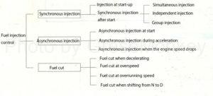
Synchronous injection
Injection at start-up
Since the inlet manifold pressure and the intake air amount are unstable when the engine is started, if the calculation is performed based on the signals, the fluctuation of the fuel injection time becomes large.
Therefore, the starting injection time is determined by the basic starting injection time determined by the cooling water temperature and the intake air temperature correction and voltage correction regardless of the inlet manifold pressure and engine rotation speed, and the starting injection time is expressed by the following formula. Will be done.
Start-up injection time (T) = Start-up basic injection time (Tp) x Intake temperature correction coefficient (K) + Voltage correction time (Tv)
Whether or not the engine is starting is determined by the engine speed and the starter signal.
Synchronous injection after start
- Calculation formula for synchronous injection after start
After starting the engine, the basic injection time determined by the inlet manifold pressure signal or intake air amount signal and engine rotation signal, and the correction and voltage correction by the signals from each sensor, determine the synchronous injection time after starting by the following formula. Will be done.
Synchronous injection time after start (T) = Basic injection time (Tp) x Injection correction coefficient (Km) + Voltage correction time (Tv)
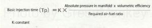
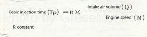
- Basic injection time calculation formula
The basic injection time is calculated from the inlet manifold pressure, the intake air amount, or the like, and is the most basic injection time stored in the control unit in advance as a map.
-
- D Jetronic method
The basic injection time (Tp) is selected from the values calculated by the inlet manifold pressure, which are stored in advance in the control unit as a map correlated with the engine speed. (Vacuum sensor compatible)
-
- L Jetronic method
The basic injection time (Tp) is determined by the following calculation based on the intake air amount detected by the air flow meter and the engine rotation speed detected by the crank angle sensor. (Compatible with air flow meters)
Calculation formula of injection correction coefficient
The electronic control device is based on the signals from each sensor when the engine state is starting, warming up, accelerating, heavy load, etc., in order to ensure optimum operation under various conditions. The basic injection time is corrected.
The correction coefficient (Km) includes an intake air temperature correction coefficient, a warm-up increase correction coefficient, a post-start increase correction coefficient, an output increase correction coefficient, an air-fuel ratio feedback correction coefficient, and the like.
The correction coefficient (Km) is generally expressed as follows by the sum or product of various correction coefficients (K1, K2, … Ka, Kb …).
Injection correction coefficient (Km) = 1 + K1 + K2 … × (1 + Ka + Kb …)
Post-start increase correction
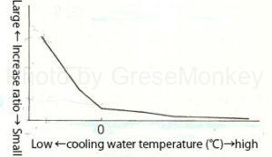
Figure 7: Post-start increase correction characteristics
When the engine is started, the injection amount is corrected according to the cooling water temperature to stabilize the engine rotation speed immediately after the start.
The increase ratio is determined by the cooling water temperature at the time of starting as shown in FIG. 7, and gradually decreases as the number of injections increases.
Warm air increase correction
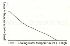
Figure 8: Warm-up increase correction characteristics
To ensure cold operability, the injection amount is corrected according to the cooling water temperature.
The increase ratio increases as the cooling water temperature is lower, as shown in Fig. 8.
Intake temperature compensation
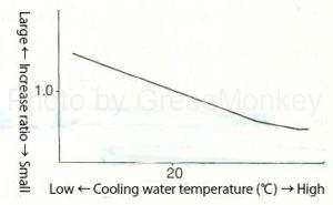
Figure 9: Intake temperature compensation characteristics
Since the air-fuel ratio deviates due to the difference in intake air density due to the intake air temperature, the injection amount is corrected by the signal from the intake sound sensor.
The increase ratio becomes larger as the intake air temperature is lower as shown in FIG.
Transient space-time fuel economy correction
The weight is increased and decreased during transitional periods such as acceleration and deceleration to improve drivability and fuel efficiency.
In the D-Jetronic method, acceleration and deceleration are determined by the amount of change in the inlet manifold pressure signal per unit time.
In the L-Jetronic method, acceleration and deceleration are determined based on the amount of change in the throttle valve opening or the amount of change in the intake air amount per engine revolution.
Output increase correction
The output range is detected by the inlet manifold pressure or intake air amount, engine speed and throttle valve opening, and the amount is increased according to the engine operating condition. Increase the throttle valve opening when it exceeds the specified value.
Air-fuel ratio feedback correction
When the air-fuel ratio is smaller (darker) than the theoretical air-fuel ratio, the O2 sensor has a higher electromotive force, and when it is larger (lighter), it becomes lower, and the signal is input to the control unit.
The control unit compares this signal with the reference voltage to determine whether it is smaller or larger than the stoichiometric air-fuel ratio.
If it is smaller than the stoichiometric air-fuel ratio, the injection amount is reduced at a constant rate. (Richburn)
If it is larger than the stoichiometric air-fuel ratio, the injection amount is increased. (Lean burn)
Hereinafter, FIG. 10 shows an example of air-fuel ratio feedback correction.
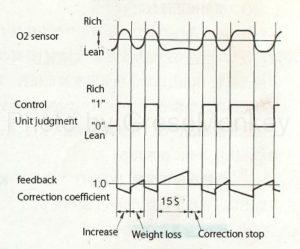
Figure 10: Air-fuel ratio feedback correction
In order to ensure safety such as operability and prevention of catalyst overheating, the air-fuel ratio feedback correction is stopped under the following conditions.
- When starting the engine
- Increasing after starting
- When the cooling water temperature is low
- When switching between the rich signal and lean signal of the O2 sensor exceeds a certain period of time (15 seconds)
- At the time of fuel cut
- When decelerating (idle contact ON)
- At high load
Voltage correction time
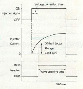
Figure 11: Valve opening time and voltage correction time
As shown in FIG. 11, there is an operation delay until the injection signal from the control unit is turned on and the injector plunger is sucked to open the valve. This operation delay time is the voltage correction time and is affected by the battery voltage.
When the injection signal ON time for operating the injector is constant, the time for the injector to open is short when the battery voltage is high, and conversely it is long when the battery voltage is low. As a result, the valve opening time of the injector is different, the injection amount is increased or decreased, and the air-fuel ratio is deviated.
Therefore, in order to keep the injector valve opening time constant, it is necessary to make the injection signal short when the battery voltage is high and long when the battery voltage is low. This is voltage correction, and the voltage correction time is shorter as the battery voltage is higher and longer as the battery voltage is lower, as shown in FIG.
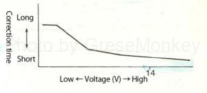
Figure 12: Voltage correction time
Injection method
Simultaneous injection method
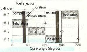
Figure 13: Simultaneous injection method
Injectors of all cylinders inject twice at the same time during one cycle. Taking the second cylinder in Fig. 13 as an example, the first fuel is discharged at a crank angle of 180 ° before (before compression top dead center). It is injected into the inlet manifold, at which point the fuel stays.
Further, the engine rotates, the second fuel is injected before the crank angle 540 ° (before the exhaust top dead center), and the fuel injected twice during the next suction stroke is sucked into the cylinder together with the air.
Although this system is simple, the responsiveness is slightly inferior because fuel stays in the inlet manifold except for the suction stroke.
Independent injection method
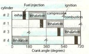
Figure 14: Independent injection method
As shown in FIG. 14, immediately before the intake stroke for each cylinder (before the exhaust top dead center), the injector of that cylinder injects fuel into the inlet manifold, and is sucked into the cylinder together with air during the suction stroke.
In this way, the required fuel is injected once per cycle for each cylinder, and the fuel is injected into the inlet manifold immediately before the suction stroke, so there is no fuel retention and the response is excellent.
Group injection method
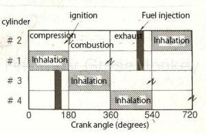
Figure 15: Group injection method
This is a method in which all cylinders are usually divided into groups of two cylinders, and each group is collectively injected once during one cycle.
In the example of FIG. 15, the injectors of the first and second cylinders inject fuel 540 ° before the crank angle (before the exhaust top dead center), and are sucked into the cylinder together with air during the suction stroke.
In this way, it is a method of injecting the required fuel once per cycle for each group, and has an intermediate feature between the simultaneous injection method and the independent injection method.
Asynchronous (simultaneous) injection
Apart from asynchronous injection, the microcomputer of the control unit calculates the input signal only immediately after the signal from each sensor is input, and when it is determined that injection is necessary, a fixed amount of injection is performed simultaneously for all cylinders. ..
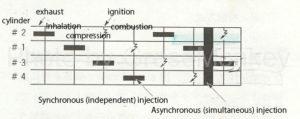
Figure 16: Asynchronous (simultaneous) injection method
FIG. 16 shows the asynchronous (simultaneous) injection of the independent injection method, and when it overlaps with the synchronous (independent) injection, the time of the asynchronous (simultaneous) injection is extended. In FIG. 16, the synchronous (independent) injection time of the third cylinder is extended.
Asynchronous (simultaneous) injection at start
Immediately after the starter signal or crank angle (rotation) signal is input, asynchronous (simultaneous) injection is performed once to improve startability.
Asynchronous (simultaneous) injection during acceleration
When the change in throttle opening is during acceleration and the amount of change is greater than or equal to the set value, asynchronous (simultaneous) injection is performed to improve responsiveness.
Asynchronous (simultaneous) injection when engine speed drops
When the engine speed drops sharply during fuel cut and when returning, asynchronous (synchronous) injection is performed to ensure operability.
Fuel cut
Fuel cut when decelerating
When the throttle valve is fully closed and the engine speed exceeds the specified value, fuel injection is stopped to prevent overheating of the catalyst and improve fuel efficiency.
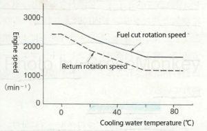
Figure 17: Fuel cut rotation speed and return rotation speed
FIG. 17 shows an example of the fuel cut rotation speed and the return rotation speed, but when the cooling water temperature is low (or when the air conditioner is ON), the rotation speed is set high.
Fuel cut when engine overspeed
When the engine speed exceeds the specified value, fuel injection is stopped to prevent the engine from overrunning.
Fuel cut when running speed is excessive
When the vehicle speed exceeds the specified value, fuel injection is stopped and the running speed is restricted. (Limiter)
Fuel cut during N-D shift
When the engine speed is above the specified value, fuel injection is stopped when the shift lever is operated to reduce shock and protect the automatic transmission.
Air-fuel ratio learning control
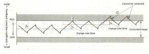
Figure 18: Changes over time in air-fuel ratio feedback correction
The control unit controls the air-fuel ratio to be close to the theoretical air-fuel ratio by the above-mentioned air-fuel ratio feedback correction.
Further, the basic injection time is set to be approximately the stoichiometric air-fuel ratio, and data is stored in the control unit, but the air-fuel ratio may deviate due to individual differences in the engine or changes over time.
If the air-fuel ratio of the basic injection amount deviates, the amount of correction by the air-fuel ratio feedback control will increase, but there is a limit to the range of correction, and if it exceeds the correction range as shown in Fig. 18C, control will become difficult. Become.
Therefore, the control unit constantly monitors whether the basic injection amount deviates from the stoichiometric air-fuel ratio and controls it so that it is always near the stoichiometric air-fuel ratio.
This is called learning control, and a learning correction coefficient is set in the control unit.
Therefore, the air-fuel ratio feedback correction amount by the O2 sensor is always a small amount.