Injection nozzle / nozzle holder
The injection nozzle (hereinafter referred to as a nozzle) is for spraying the high-pressure fuel pumped from the injection pump into the combustion chamber of the engine in the best spray state when burning.
Since the fuel injected into the combustion chamber must ignite immediately and burn in a short time, the nozzle has the following characteristics.
- The fuel is made into a fine mist to facilitate ignition. (Miniaturization)
- Make sure that the atomized fuel reaches every corner of the combustion chamber. (Penetration)
- Disperse and distribute fuel spray over a wide area. (Dispersion / distribution)
- At the end of the injection, the fuel is completely shut off and no one is left behind. (Oiltightness)
The nozzle holder has the function of attaching and holding the nozzle to the engine, guiding the fuel to the nozzle, and returning the fuel that lubricates the needle valve and the nozzle body to the fuel tank by the return pipe.
Further, the nozzle holder is provided with a mechanism for adjusting the fuel injection start pressure.
Injection nozzle
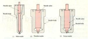
Figure 1: Nozzle type
As shown in FIG. 1, the nozzle is composed of a nozzle body and a needle valve (needle valve), and the types include a hole nozzle, a throttle nozzle, and a focus toe nozzle.
Hole nozzle
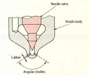
Figure 2: Hall nozzle
As shown in FIG. 2, the hole nozzle has a conical tip of the needle valve, and the nozzle body is provided with several nozzles.
This nozzle is used in direct injection engines and has an injection starting pressure of 17-23 MPa.
The nozzle is generally provided at the tip of the nozzle body at a certain angle (nozzle angle) with respect to the nozzle for the purpose of obtaining a spread of fuel suitable for combustion of the engine.
The number of nozzles and the diameter of the nozzles are designed according to the performance of the engine so as to be suitable for the size of the spray particles and the reach of the spray.
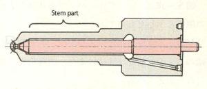
Figure 3: Shape of stem
Further, in order to enhance the cooling effect, the shape of the stem portion is lengthened as shown in FIG. 3 to increase the contact area with the cylinder head (water jacket portion).
Throttle nozzle
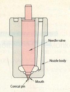
Figure 4: Throttle nozzle
The throttle nozzle is a nozzle provided with a mechanism to throttle the injection amount at the initial stage of injection. As shown in Fig. 4, there is only one nozzle, and the tip of the needle valve is a conical pin slightly thinner than the nozzle nozzle. ..
This nozzle is mainly used in vortex chamber type engines, and the injection start pressure is 10 to 14 MPa.

Figure 5: Throttle nozzle operation
Fig. 5 shows the operation of the throttle nozzle. When the pressure of the fuel sent from the injection pump reaches the injection start pressure of the nozzle, the needle valve starts to rise as shown in Fig. 5 (2), and the injection port Fuel injection starts from the part.
Since the fuel is injected through the gap between the nozzle and the pin of the needle valve, the nozzle area is narrowed and small at the initial stage of injection, so that only a small amount of fuel is injected. This is called the throttle stroke.
Further, when the needle valve is pushed up, the nozzle area becomes maximum as shown in FIG. 5 (3), and the main injection is performed.
In this way, the reason for changing the nozzle area is that if the vaporized state of the injected fuel from the injection of the fuel to the ignition is poor, sudden rapid combustion will occur temporarily and abnormal combustion such as diesel knock will occur. This is to prevent it from happening.
As a method of preventing the occurrence of abnormal combustion, a throttle stroke is provided to reduce the injection amount during the period in which abnormal combustion can occur, and by facilitating the vaporization of fuel, rapid combustion is suppressed.
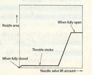
Figure 6: Relationship between needle valve lift and nozzle area
FIG. 6 shows the relationship between the lift amount of the needle valve and the nozzle area. In the throttle nozzle, the injection angle and the throttle stroke are changed according to the shape and dimensions of the pin at the tip of the needle valve.
Focus nozzle
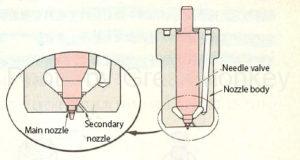
Figure 7: Focus nozzle
The focus toe nozzle has a secondary nozzle on the nozzle body and is mainly used in a vortex chamber type engine.
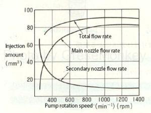
Figure 8: Injection amount of focus nozzle
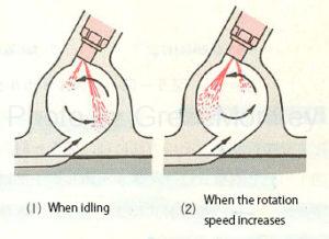
Figure 9: Focus nozzle injection
FIG. 8 shows the relationship between the injection pump rotation speed of the focus nozzle and the injection amount per plunger stroke.
When idling, the throttle stroke time becomes long, so as shown in Fig. 9 (1), fuel is injected in the direction facing the air flow by the sub-injection port, and the mixture with compressed air is optimized to improve ignitability. ..
Further, as the rotation speed increases, the throttle stroke time becomes shorter, so that most of the injection is performed from the main injection port as shown in FIG. 9 (2).
* Throttle stroke = idling stroke
Nozzle holder
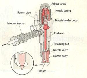
Figure 10: Nozzle holder
The nozzle holder is equipped with a mechanism for attaching the nozzle to the cylinder head, introducing fuel to the nozzle, and adjusting the fuel injection start pressure of the nozzle. As shown in Fig. 10, the inlet connector, nozzle spring, adjust screw, and nozzle are provided. It consists of a holder and a nozzle body.
Fuel enters the inlet connector and flows to the bottom of the needle valve on the nozzle body as shown by the arrow in Figure 10.
When the pressure of the fuel sent to the nozzle reaches the injection start pressure, it overcomes the spring force of the nozzle spring and pushes down the needle valve to inject the fuel.
In addition, a part of the fuel lubricates the needle valve and the nozzle body, and returns from the return pipe to the fuel tank through the gap between the push rod and the nozzle holder stay via the nozzle spring chamber.
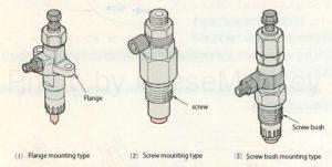
Figure 11: Types of nozzle holders depending on how they are attached
As shown in FIG. 11, there are three types of nozzle holders, a flange mounting method, a screw mounting method, and a screw bush mounting method, depending on the mounting method to the cylinder head.
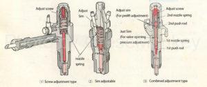
Figure 12: Types of nozzle holder injection start pressure adjustment method
The fuel injection start pressure is adjusted by changing the load applied to the nozzle spring (spring force of the nozzle spring), and the method is as shown in FIG.
The screw adjustment type shown in FIG. 12 (1) is adjusted by an adjustment screw provided on the upper part of the nozzle holder, and is used for an engine having a direct injection type and a vortex chamber type combustion chamber of a large vehicle. Figure 12 (1) shows the one used in the vortex chamber type.
The shim adjustment type shown in FIG. 12 (2) is adjusted by an adjust shim, and since the total length of the nozzle holder can be shortened, it is used for an engine having a vortex chamber type combustion chamber of a small car.
The combined adjustment type shown in Fig. 12 (3) is a combination of adjustment using an adjust screw and an adjust shim. It is called a 2-spring nozzle holder and is used for engines with a direct injection combustion chamber of large vehicles.
Fuel filter
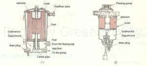
Figure 13: Fuel filter
The fuel filter is attached to the engine body or the body of the engine room, and is composed of a case, an element, a center pipe, a cover, an overflow valve, a drain plug, etc. as shown in FIG. 13 (1).
Types of elements include filter paper type and filter cloth type, but the filter paper type is generally used. The element of FIG. 13 (1) is a filter paper type, and the filter paper is bent into a tubular shape to increase the filtration area.
In addition, a segmenter portion for separating fuel and water is provided at the lower part of the fuel filter, and water is discharged by a drain plug.
Further, FIG. 13 (2) shows a fuel filter mainly used for passenger cars, which also has a priming pump for bleeding air.
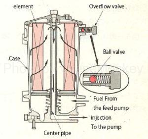
Figure 14: Fuel flow in the fuel filter
The fuel pumped from the feed pump enters between the case and the element as shown in FIG. 14, passes through the element, is filtered, and is sent out from the outlet to the injection pump through the center pipe.
When the fuel pressure of the fuel filter exceeds the specified value due to clogging of the element, the overflow valve is activated, and the fuel pushes open the ball valve, passes through the return pipe, and is returned to the fuel tank.
Further, even when air is mixed in the fuel, the overflow valve is activated and the mixed air is discharged from the return pipe together with the fuel.
Fuel tank
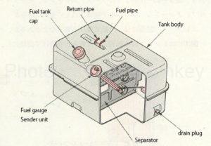
Figure 15: Fuel tank
As shown in FIG. 15, the fuel tank is composed of a tank body, a fuel tank cap, a fuel gauge sender unit, a drain plug, and the like.
The inner surface of the tank body is rust-proofed, and a drain plug is attached to the lower part so that moisture and dust in the tank can be discharged.
In addition, a separator is provided to reduce the fluctuation of the fuel and increase the strength.
Fuel hose pipe
Fuel hoses and pipes are divided into those extending from a fuel tank to a feed pump, a fuel filter and an injection pump, and those extending from an injection pump to an injection nozzle.
In particular, for hoses and pipes leading to injection, injection pipes having excellent pressure resistance are used because the fuel becomes high pressure.