Disc brake basics
Table of Contents
Disc brake
Disc brakes. Because of its excellent cooling performance and stable braking force even at high speeds, it is used almost 100% on the front wheels of passenger cars.
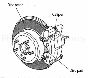
Figure 1: Disc brake configuration
The operating principle of the disc brake is a mechanism in which a braking force is obtained by strongly clamping the disc rotor with a pad. Therefore, it is composed of a disc rotor, a pad for sandwiching the disc rotor, and a caliper containing a piston and a cylinder for pushing the disc rotor.
The caliper includes a floating caliper type (floating caliper type) in which the caliper moves when activated, and an opposing piston type (fixed caliper type) in which the caliper does not move.
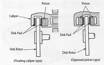
Figure 2: Types of calipers
The floating caliper type has only one piston on one side, and when brake hydraulic pressure is applied, the piston is pushed out and the caliper moves with the cylinder to the opposite side, so the pads on both sides crimp across the disk rotor . This operation is the reason why it is called a following (floating) caliper type.
The floating caliper type can be mounted on narrow wheels, so it is often used for small cars.
On the other hand, the opposing piston type requires more space, but the response (response) is good and the caliper rigidity can be increased, so the opposing piston type is often used in high-performance vehicles. .
Floating caliper type structure
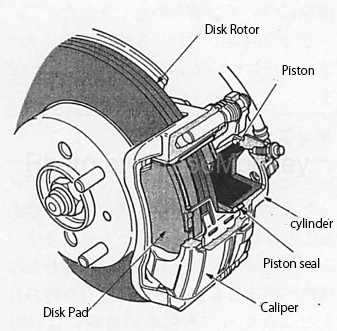
Figure 3: Floating caliper type structure
The floating caliper type includes a disc rotor, a caliper that slides in a lateral direction, one cylinder and a piston provided on one side of the caliper, a pad that sandwiches the disc rotor, and the like.
Opposed caliper type structure
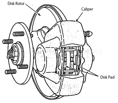
Figure 4: Counter-piston type structure
The opposed caliper type is composed of a disc rotor and a fixed caliper, and cylinders are attached to both sides of the caliper. When the brake oil pressure is applied, the piston, that is, the pad, is pushed out from both sides to pinch the disk rotor and generate a braking force.
Tuning the disc brake
In high-performance cars, 4-piston calipers and 6-piston calipers are no longer uncommon. Although it looks high in performance from the appearance, it is not adopted from the appearance. What benefits can be gained by increasing the number of pistons?
As a means for improving the performance of a disc brake, there is a method called “enlargement of a disc rotor”. So why do we need to enlarge the disk rotor? ?
Larger disk rotor
The braking force generated on the ground contact surface of the tire is smaller than the braking force generated on the friction surface of the pad by a ratio of the effective radius of the disc rotor to the effective radius of the tire due to the leverage principle.
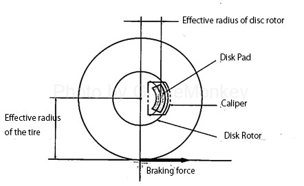
Figure 5: Effective radius of the disc rotor
Therefore, if the size of the disk rotor can be increased and the effective radius of the disk rotor can be increased, the braking force generated on the friction surface of the pad, that is, the pressing force of the pad can be reduced.
For that purpose, it is necessary to increase the diameter of the wheel that accommodates the disk rotor. Therefore, it is necessary to increase the diameter of the tire or increase the flatness of the tire to increase the diameter of the wheel. However, these measures cannot be freely executed because they are subject to restrictions such as interference with the vehicle body and deterioration of ride comfort.
The method of increasing the effective radius of the disk rotor without changing the diameter of the disk rotor can be realized by increasing the number of caliper pistons. In fact, it seems that the increase in the diameter of the disc rotor and the increase in the number of caliper pistons are adopted at the same time.
More caliper pistons
To increase the braking force, there is an idea to increase the pressure receiving area of the caliper piston. However, if the pressure receiving area of the piston is increased, the effective radius of the disk rotor (the distance from the center of the disk rotor to the center of the piston) decreases. The problem that occurs.
Therefore, the effective radius of the disk rotor can be increased by making the pad slender without changing the pressure receiving area of the piston with two pistons on each side. The so-called 6-piston caliper is a further development of this concept, with three pistons on each side. (Fig. 6)

Figure 6: Expansion of effective radius of disc rotor by twin piston
One of the features of the disc brake is that there is no cell portion servo action unlike a drum brake, and a stable braking force proportional to the pedaling force can be obtained even at a high speed. However, in practice, there is some self-servo, and the force for slightly pressing the inlet side (leading side) against the rotation of the disk rotor increases. (Figure 7)
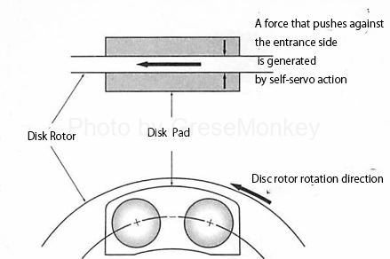
Figure 7: Self-servo action of twin-piston disc brakes
Therefore, there is a case where the piston on the inlet side is made slightly smaller to equalize the pressing force of the pad. (Fig. 8)
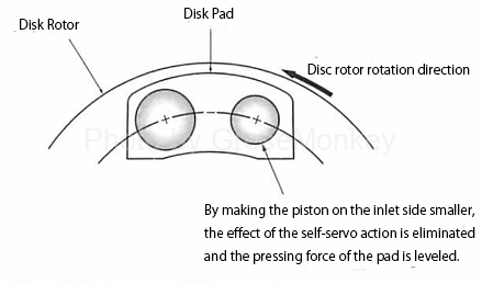
Figure 8: Effect of deformed piston
Cylinder and piston
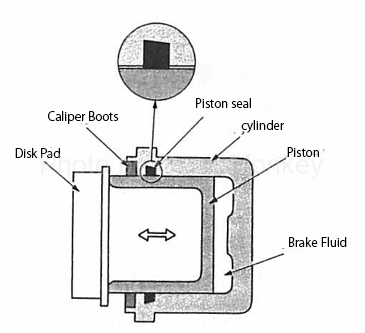
Figure 9: Cylinder and piston assembly
The cylinder and the piston are mounted on the caliper so as to sandwich the disc. A soft rubber boot is incorporated at the end of the cylinder to prevent moisture and foreign matter from entering the piston. (Fig. 9)
At the back of the boot, a rubber piston seal is housed in a groove on the inner wall of the cylinder, and the seal holds brake hydraulic pressure.
Automatic adjustment device
The automatic adjusting device always keeps a constant gap with the disk rotor even when the pad is worn, and the actual adjustment of the gap is performed by a piston seal when the brake is operated / released.
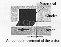
Figure 10: Piston seal operation (when hydraulically operated)
When the brake is activated, the piston is pushed out while deforming the piston seal, applying pressure to the pad. (Figure 10)
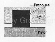
Figure 11: Piston seal activation (when hydraulic pressure does not operate)
When the brake oil pressure is no longer applied, the piston seal returns to its original shape, so that the piston is pulled back by that amount, and a gap is maintained between the piston seal and the disc rotor. (Fig. 11)
When the displacement of the piston increases due to wear of the pad, the amount of deformation of the piston seal also increases. However, when the amount of deformation exceeds a specified value, the piston slides on the piston seal by that amount. When the brake is released, the piston seal returns to the original shape, so that only the prescribed deformation is pulled back, and the gap is kept constant. That is, the position of the piston when the pad is returned by the amount worn is gradually protruding.