Idle rotation speed controller / ISCV
Since the throttle valve of the idle rotation control device is fully closed during idle rotation, an idle speed control valve (hereinafter, ISCV) is provided in the bypass passage, and signals from each sensor are provided as shown in the system diagram of FIG. The control unit calculates an appropriate idle rotation speed to operate the ISCV, bypasses the throttle valve, and changes the amount of intake air flowing to control the idle rotation speed.
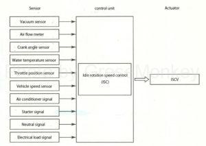
Figure 1: System diagram of idle rotation speed controller
ISCV type
Rotary valve type
As shown in Fig. 2, the rotary valve type ISCV is composed of a rotary solenoid composed of a solenoid coil, a magnet that tilts in the direction of rotation, and a valve that controls the amount of air.
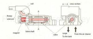
Figure 2: Rotary valve ISCV
As shown in Fig. 2, the valve has a structure that moves in the direction of rotation to open and close the intake air passage by rotating the valve shaft that moves integrally with the magnet, and opens by duty-controlling the magnitude and direction of the current flowing through the coil. Is now controlled.
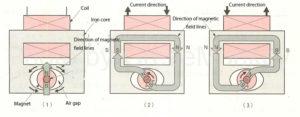
Figure 3: Operating principle of rotary solenoid
Figure 3 illustrates the principle of valve shaft rotation.
In Fig. 3 (1), the magnet is placed in the center of the iron core hollowed out in an ellipse, and the north and south poles have the strongest magnetic force and are attracted to the part with the smallest gap. It is fixed in a proper position.
Further, since a coil is wound around the iron core, when an electric current is passed through the coil, it becomes an electromagnet and a magnetic field is generated.
Now, when a current is applied as shown in Fig. 3 (2) so that the right side of the iron core is the north pole, the south pole of the magnet is on the north pole side of the iron core, and the north pole of the magnet is on the south pole side of the iron core. To attract, the magnet tilts counterclockwise and the valve shaft tilts by the same angle.
Next, when the direction of the current is changed in the opposite direction as shown in Fig. 3 (3), the S pole and N pole of the iron core are reversed, so the magnet also tilts in the opposite direction.
- Duty control
The duty control in this case is the control of the ON / OFF time of the current in the energizing time of the coil, and the ON / OFF is repeated in units of several hundred Hz.
The duty ratio is the ratio of the ON time to the OFF time. For example, the duty ratio of 60% means that the time when the current is flowing is 60% and the time when the current is not flowing is 40%.
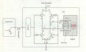
Figure 4: Rotary valve ISCV control circuit
Figure 4 is an example of an actual circuit.
The transistors Tr1 and Tr4 operate when the duty signal is ON. Tr2 and Tr3 are transistors that operate when the duty signal is OFF.
- When the duty ratio is 50%
The state of the magnet position in FIG. 4 is a state when the duty ratio is 50%, that is, a state in which no current is flowing through the coil described above.
When the duty ratio is 50%, when a 50% duty signal is output from the control unit, a current flows from the IC circuit to the bases of Tr1 and Tr4, and both transistors are turned on.
The current from the battery is grounded from Tr4 through the coil from Tr1 as shown by the solid arrow, and the iron core is an electromagnet with N pole on the lower side and S pole on the upper side.
Then, the magnet tries to tilt the south pole to the lower side and the north pole to the upper side in the clockwise rotation direction, but since the duty control is as fast as several hundred Hz, the duty signal is turned off at that moment. However, since it tilts as it is, the base current flows from the IC circuit to Tr2 and Tr3 via the NOT circuit and is grounded from Tr2.
At this time, contrary to the above-mentioned case, the magnetic pole of the iron core has an N pole on the upper side and an S pole on the lower side, and the magnet tries to tilt in the opposite direction, but because the duty control is fast, it stops at the center as shown in the figure. ..
As a result, the magnetic poles of the magnet do not move from the center in order to repeat the operation of the upper and lower iron cores switching to the N and S magnetic poles at high speed for the same time.
- When the ON time is long (duty ratio is large)
When the ON time is long (the duty ratio is large), the magnet tilts in the clockwise direction because the magnetic pole on the upper side of the iron core stays at the S pole for a long time.
- When the OFF time is long (duty ratio is small)
When the OFF time is long (duty ratio is small), the magnet tilts in the counterclockwise direction because the upper side of the iron core is in the N pole for a long time.
That is, as shown in FIG. 5, it is controlled between fully closed and fully open according to the duty ratio.
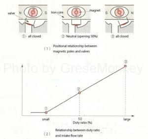
Figure 5: Relationship between duty ratio, valve opening and intake flow rate
Step motor type
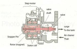
Figure 6: Step motor ISCV
As shown in Fig. 6, the step motor type ISCV consists of a step motor consisting of a stator coil and a rotor, and a valve.
- Operating principle of step motor
The operating principle of the step motor is that the rotor (permanent magnet) moves the magnetic force of the stator coil by changing the excitation of the stator coil in order in the stator coil and rotor (permanent magnet) arranged regularly as shown in Fig. 7. Is designed to rotate by a certain number of steps.
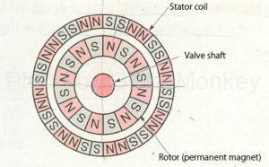
Figure 7: Step motor operating principle
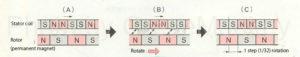
Figure 7: Step motor operating principle
When the excitation of the stator coil is shifted from A to B as shown in Fig. 7, the electromagnets of the stator coil and the permanent magnets of the rotor N and S attract each other, and N and N and S and S repel each other. The rotor rotates one step to the C position.
In an actual step motor, the rotor is made of magnets excited to 16 poles in total of N and S as shown in Fig. 7, and the stator has 32 magnetic poles in total of N and S.
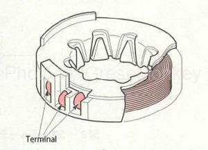
Figure 8: Step motor stator
Actually, as shown in Fig. 8, two coils with 16-pole cores are used, two coils with different winding directions are wound on one stator, and all four magnetic poles are mounted out of phase. is there.
Therefore, in one rotation of the rotor, it moves by 32 steps, which is the number of magnetic poles of the stator coil.
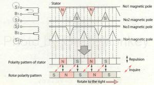
Figure 9: Stator polarity pattern (when S1 is energized)
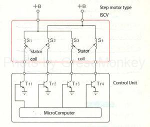
Figure 10: Step motor type ISCV control circuit
In the control circuit shown in FIG. 10, since the microcomputer of the control unit sends the output current in the order of Tr1, Tr2, Tr3, and Tr4 to the base and stops it, each transistor repeats ON and OFF, and 1 for the four coils. The current flows one by one and stops.
That is, in FIG. 9, when a current is passed through S1 of the stator coil, the No1 magnetic pole becomes the N pole and the No3 magnetic pole becomes the S pole as shown in the figure. This time, the No. 2 magnetic pole becomes the N pole and the No. 4 magnetic pole becomes the S pole, and the process proceeds two steps.
From this state, when the current of S2 is stopped and then the current is passed through S3, the No3 magnetic pole becomes the N pole and the No1 magnetic pole becomes the S pole. Then, No4 becomes the N pole and No2 becomes the S pole, and it advances 4 steps, and it rotates one step at a time.
When rotating this in the reverse direction, the current should be passed in the reverse order of S2, S1, S4, and S3 from the state shown in Fig. 9.
The rotor and valve shaft are in a nut-bolt relationship, and as the rotor rotates, the shaft moves in the axial direction, and the valve controls the amount of air by widening or narrowing the bypass passage. ing.
Control by control unit
The control unit stores the target idle rotation speed according to each condition such as cooling water temperature and air conditioner operation. Based on the input signal from each sensor, the idle rotation speed is controlled to reach the target value.
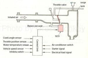
Figure 11: ISCV system diagram
FIG. 11 is an example of the ISCV system diagram, in which the amount of air flowing in the bypass passage of the throttle body is adjusted by the ISCV according to the signal from each sensor, and the idle rotation speed is controlled.
Start-up control
At start-up, the ISCV intake air volume is maximized. Therefore, if the engine is started in that state, the rotation speed may be too high, so the opening degree of the ISCV is determined according to the cooling water temperature at the same time as the start.
FIG. 12 shows an example of the relationship between the cooling water temperature and the opening degree of ISCV.
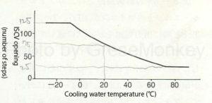
Figure 12: Relationship between cooling water temperature and ISCV opening
Warm-up control
After the control at the start is completed, the ISCV is gradually closed according to the cooling water temperature to control the fast idle rotation speed.
Predictive control
When the shift lever of the AT mission is switched, the air conditioner switch is switched, or the electric load changes significantly, the load applied to the engine changes, so the idle speed also changes.
Therefore, immediately after detecting these signals, the ISCV signal is sent in advance before the rotation fluctuates, the required air amount is predicted, the ISCV opening is changed, and the idle rotation speed is maintained appropriately. I’m trying.
Feedback control
If the idle speed after warm-up is different from the target speed, a signal is sent to the ISCV to recontrol the target idle speed.