Manual air conditioner and auto air conditioner
As shown in Fig. 1, the car air conditioner basically uses the functional parts of the heating device and the cooling device, and the heat exchangers (heater core, evaporator) are housed in the same case for each. The blowout temperature can be controlled not only for heating and cooling but also for intermediate temperatures.
Therefore, when the temperature is low and the humidity is high, a comfortable environment without a feeling of cooling can be created by lowering the temperature with an evaporator to condense and dehumidify the moisture in the air and warming with a heater core.
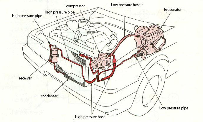
Figure 1: Air conditioner
table of contents
- Classification by control method of car air conditioner
- Classification by the arrangement method of heat exchangers of car air conditioners<
- Basic structure and function of car air conditioner
- Functional parts that make up the air conditioner cycle
- Manual air conditioner
- Auto air conditioner
- Auto air conditioner blowout temperature control system
- Auto air conditioner air volume control system
Classification by control method of car air conditioner
- Manual air conditioner
The set temperature of the air conditioner selects whether to strengthen the heating or cooling function according to the temperature conditions at that time.
In the manual air conditioner, the method of strengthening this heating / cooling function is adjusted by the temperature setting lever to adjust the blowout temperature.
- Auto air conditioner
When the temperature inside the vehicle is set to the desired temperature, the auto air conditioner automatically corrects the temperature changes inside and outside the vehicle and the effects of solar radiation by the control unit, and controls the temperature inside the vehicle so that it is always kept at the set temperature.
Classification by the arrangement method of heat exchangers of car air conditioners
- Air mix method
As shown in Fig. 2, there is an air mix damper between the evaporator and the heater core, and the amount of air cooled by the evaporator is controlled by the degree of opening of this damper to the heater core side and to the outlet. Then, both airs are mixed in the air mix chamber to adjust the temperature.

Figure 2: Heat exchanger placement method (1)
- Reheat method
As shown in Fig. 3, all the cold air that has passed through the evaporator flows to the heater core, and the amount of hot water that flows to the heater core is controlled by the water valve, and the temperature is adjusted by how much the cold air is warmed. ing.
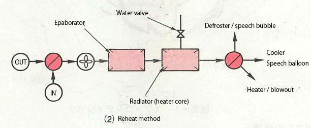
Figure 3: Heat exchanger placement method (2)
Basic structure and function of car air conditioner
The figure below shows the positions and roles of typical functional parts that make up the refrigeration cycle of an air conditioner, and how a car air conditioner circulates and cools the refrigerant.
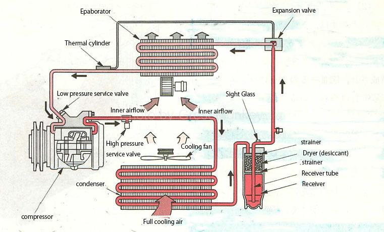
Figure 4: Car air conditioner refrigeration cycle
[:ja]カーエアコンの基礎を見直す[:en]Review the foundation of car air conditioners[:]
Functional parts that make up the air conditioner cycle
compressor
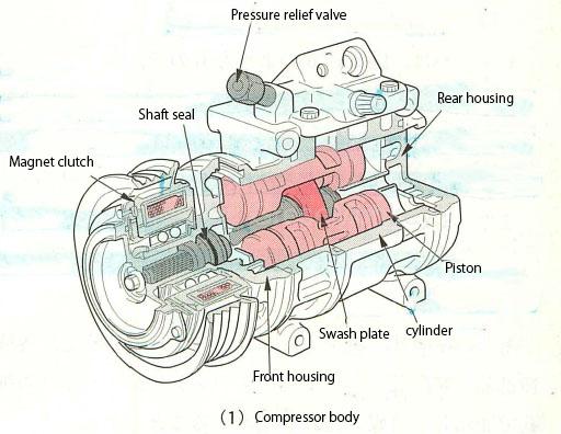
Figure 5: Slanted plate compressor body
As shown in Fig. 5, the compressor (swash plate type) moves the piston left and right by rotating the swash plate to suck, compress, and send out the refrigerant. Three pairs (6 cylinders) or 5 pairs (10 cylinders) of pistons. However, it is set diagonally with respect to the shaft by the swash plate.

Figure 6: Swashplate compressor operation
In this type of compressor, when the shaft rotates, the piston reciprocates in the same direction as the shaft by the swash plate as shown in FIG.
Cylinders are arranged on both sides of the pair of pistons, and when one side is in the compression stroke, the other side is the suction stroke, and each stroke cycle is determined by the number of cylinders.
condenser
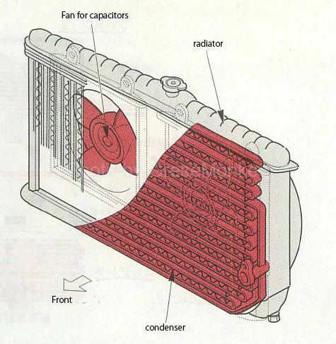
Figure 7: Capacitor
The capacitor is for cooling the high-temperature and high-pressure gaseous refrigerant pumped from the compressor into a liquid refrigerant. It is composed of tubes and fins, and unlike the radiator of cooling water, it does not have an upper tank and a lower tank. Further, as shown in FIG. 7, it is attached to the front surface of the radiator, and the high-temperature and high-pressure gaseous refrigerant passing through the tube is converted into a liquid refrigerant by the cooling action generated by the condenser fan and the front cooling air generated by running passing through the fins. I’m urging you to do it. (See Figure 4 = link)
An electric fan (condenser fan) is installed to cool the condenser, but the rotation speed of the electric fan is controlled in 2 to 3 stages by the pressure in the refrigeration cycle and the cooling water temperature (water temperature in the radiator). There is.
Lacyva Sightglass
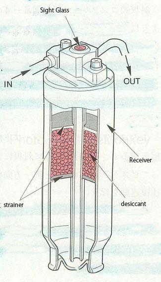
Figure 8: Receiver and sight glass
The receiver has a structure as shown in Fig. 8, and the refrigerant liquefied by the condenser is temporarily stored so that it can be supplied to the evaporator according to the cooling load. The gas and liquid in the refrigerant are stored. It serves to separate.
In addition, a strainer and a desiccant are sealed inside the receiver in order to remove dust and moisture in the refrigeration cycle.
Moisture during the refrigeration cycle may corrode each functional component or cause freezing in the pores of the expansion valve, impeding the flow of refrigerant.
The sight glass is a “peep window” that observes the state of the refrigerant flowing during the refrigeration cycle. Generally, when bubbles can be seen from this window, the refrigerant is insufficient, and when the bubbles cannot be seen, the amount of refrigerant is Indicates that is the proper amount. (It is just a guide.)
The sight glass is attached to the upper part of the receiver as shown in the figure, but when it cannot be used at the upper part due to the mounted state of the receiver, a single one attached in the middle of the piping is used.
Expansion valve / evaporator
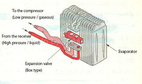
Figure 9: Expansion valve (box type)
The expansion valve is as shown in Fig. 9, and has the following two functions.
- By injecting a high-temperature, high-pressure liquid refrigerant that has passed through the receiver through a very small hole, it is rapidly expanded to become a low-temperature, mist-like refrigerant, which is then injected into the evaporator.
- The amount of refrigerant is adjusted according to the vaporization state of the refrigerant in the evaporator.
In order to fully utilize the capacity of the evaporator, the liquid refrigerant must take away heat from the surroundings and always keep it in a state where evaporation is completed at the outlet of the evaporator.
For that purpose, the amount of the refrigerant is automatically adjusted according to the fluctuation of the vehicle interior temperature (cooling load) and the fluctuation of the compressor rotation speed.
The basic mechanism for adjusting the amount of refrigerant is the opening and closing of the diaphragm chamber of the expansion valve and the needle valve directly connected to it.

Figure 10: Expansion valve activation
In FIG. 10, the refrigerant gas is sealed in the A chamber of the diaphragm chamber.
The pressure in chamber A is high when the refrigerant temperature near the outlet of the evaporator is high, and low when the temperature is low.
In the box type of Fig. 10 (1), the temperature is transmitted to the gas in room A by the temperature sensitive rod to change the gas pressure, and in the conventional type of Fig. 10 (2), the gas in room A is directly used by the gas in the heat sensitive cylinder. The pressure changes.
On the other hand, the evaporator evaporating pressure is applied to the chamber B from the vicinity of the evaporator outlet.
Explaining the basic operation, in FIG. 10, when a constant amount of refrigerant is flowing, the diaphragm keeps the needle valve at a constant opening by the pressure of chambers A and B and the force of the spring. However, when the cooling load (room temperature, etc.) fluctuates, the pressure in room A changes, and the needle valve is moved left and right to adjust the amount of refrigerant and control the supply of refrigerant to the evaporator.
Manual air conditioner
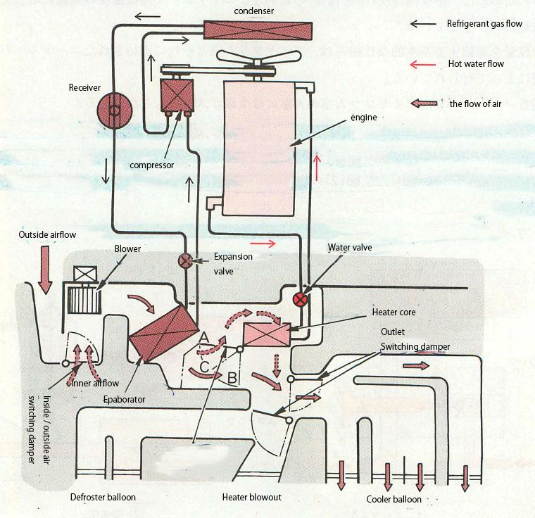
Figure 11: Manual air conditioner (air mix type)
In FIG. 11, the air flowing by the rotation of the blower is deprived of heat when flowing through the evaporator, becomes cold, and flows toward the radiator (heater core).
There is an air mix damper between the evaporator and the heater core, and its opening angle can be adjusted by the temperature control lever.
When the temperature is set to the maximum cooling position, the air mix damper closes the position (A), that is, the passage to the heater core, and all the cold air is blown out through the air mix chamber without being warmed. It flows from the mouth into the room to cool it.
Next, if the temperature is set to the maximum cooling position, the air mix damper will be in the position (B), and all the cold air will pass through the heater core, so it will be warmed here and flow into the room to heat it. conduct.
If the temperature setting lever is set to the intermediate position, the air mix damper will be in the position (C), and part of the cold air will flow to the air mix chamber as it is, and part of it will flow to the heater core to become warm air. It flows to the mix chamber, where air with two temperatures, high and low, is mixed and flows into the room from the outlet to adjust the room temperature.
In this way, in the air mix method, the amount of hot air and cold air is controlled by operating the air mix damper to adjust the room temperature.
The outlet is selected by operating the lever of the outlet switching damper.
Auto air conditioner
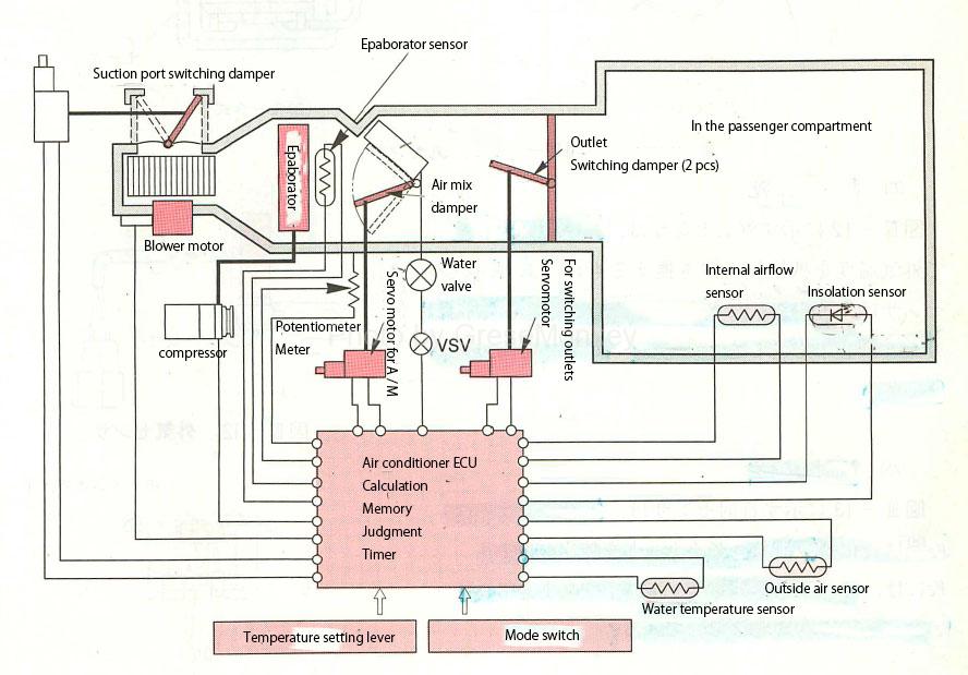
Figure 12: Microcomputer type auto air conditioner system diagram
FIG. 12 is a control system diagram of an automatic air conditioner by ECU control.
A signal of the set temperature is sent to the control unit by the temperature setting lever, and the room temperature, the amount of solar radiation, and the outside air temperature are detected by each sensor, and the signals are input to the control unit.
The control unit controls the room temperature by determining the operation of the auto air conditioner, that is, “opening of the air mix damper, switching of air volume, switching of suction port and outlet, control of compressor”, etc. from the input information. There is.
Auto air conditioner blowout temperature control system
Inside temperature sensor
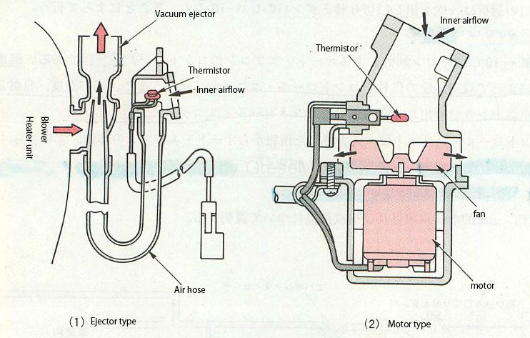
Figure 13: Inside air temperature sensor
The internal air temperature sensor shown in Fig. 13 takes in the air inside the vehicle, detects the temperature with a thermistor, replaces it with a resistance value, and sends it to the control unit. Some use an aspirator to use the air flow of the heater unit, while others use a dedicated fan motor as shown in Fig. 13 (2).
Outside air sensor

Figure 14: Outside air sensor
The outside air temperature sensor shown in FIG. 14 replaces the outside air temperature with a resistance value by a thermistor, and this sensor does not respond sensitively to sudden temperature changes such as the influence of exhaust gas from a car running outside. The outside is molded with resin.
Insolation sensor
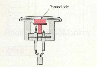
Figure 15: Solar radiation sensor
The solar radiation sensor shown in FIG. 15 uses a photodiode whose resistance value changes depending on the amount of solar radiation, and is generally attached to the upper part of an instrument panel that is easily affected by solar radiation.
Temperature setting resistor
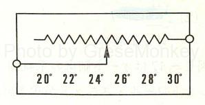
Figure 16: Set resistor
The temperature setting resistor shown in FIG. 16 is connected to the temperature setting lever, and the temperature set by the user is input to the control unit as a resistance value.
Blow-out temperature control
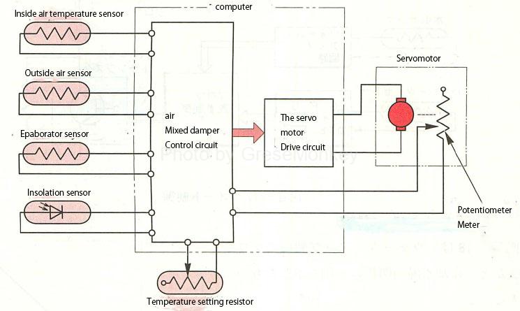
Figure 17: Block diagram for blowout temperature control
FIG. 17 is a block diagram of blowout temperature control.
The set resistance (desired temperature) set by the temperature setting lever and the signals from the internal temperature, outside air temperature, solar radiation, and evaporator sensors are input to the air mix damper control circuit.
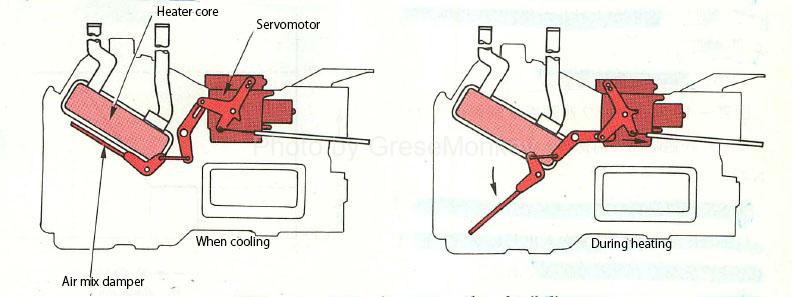
Figure 18: Operation of air mix damper
The required blowout temperature is calculated by the control circuit, the servo drive circuit is operated, and the opening degree of the air mix damper shown in FIG. 18 is controlled by the servo motor. In addition, the movement of the servo motor is detected by the potentiometer and input to the control circuit again to correct the operation.
Auto air conditioner air volume control system
Auto control
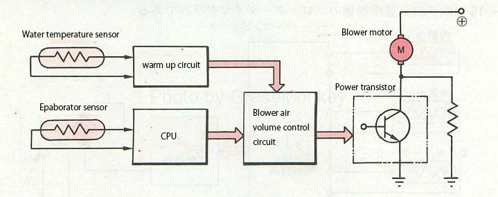
Figure 19: Auto control
FIG. 19 is a system diagram of automatic control. The control unit determines the air volume according to the blowout temperature according to the conditions such as the outside air temperature, the set temperature, and the vehicle interior temperature, and the blower motor is steplessly changed by the power transistor.
Warm-up control
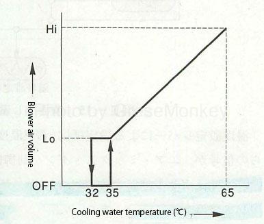
Figure 20: Warm-up control
FIG. 20 shows an example of the relationship between the blower air volume of warm-up control and the cooling water temperature.
When the cooling water temperature is low and the outlet is in FOOT mode (foot), the control is to eliminate the discomfort caused by the cold air blowing from the feet. The water temperature sensor detects the cooling water temperature and sends a signal to the blower air volume control circuit. ..
Generally, when the cooling water temperature is about 30 ° C to 40 ° C or less, the blower motor is turned off, and when the cooling water temperature is 50 ° C to 60 ° C, it is controlled by Lo, and it is automatically controlled after the water temperature rises.
Blower delayed air volume control
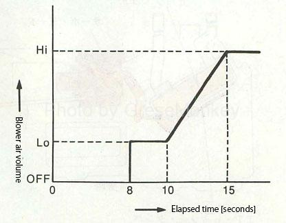
Figure 21: Blower delayed air volume control
FIG. 21 shows an example of the relationship between the blower air volume for controlling the blower delay air volume and the elapsed time.
The outlet is in FACE (face) mode, and immediately after the compressor is turned on, it is a control to eliminate discomfort to the face due to warm air blowing.
When the blower is automatically controlled after the key switch is turned on, if the air conditioner switch is turned on, the blower motor is turned off for about 8 seconds, and only the compressor is turned on to cool the evaporator. Approximately 8 seconds later, the blower motor starts at Lo and the cooled air blows out, after which it is controlled by the delay timer as shown in Fig. 21.
Blower start control
After starting the blower motor, it is controlled by Lo for about 2 seconds to protect the power transistor from the starting current.
Auto air conditioner outlet control
The outlet switching is a signal from the air mix servomotor and the control unit to operate the outlet switching servomotor and the outlet switching damper linked to this servomotor.

図22:吹き出し口制御
FIG. 22 shows an example of switching the outlet, and the outlet is automatically switched between “FACE” → “BI-LEVEL” → “FOOT” according to the temperature of the outlet that is automatically controlled. If the blowout temperature is low, it can be switched to “FACE”, if it is in the middle, it can be switched to “BI-LEVEL”, and if it is high, it can be switched to “FOOT”.
Not only can each control item such as blowout temperature and air volume be automatically controlled, but each servo motor can be controlled by the control switch on the air conditioner control panel and manually controlled arbitrarily.