2007 Mitsubishi Delica D5 Model
- DBA-CV5W Engine Model
- 4B12 MIVEC Mission Model
- W1CJA Type INVECS-IIICVT
- Travel Distance: 13,7000km

Table of Contents
- About various sensors used in Delica D5
- TPS and APS
- O2 sensor
- Pressure switch
- The role of the actuator
About various sensors adopted in Delica D5
Below is a system diagram of the fuel control system of the Delica D5 4B12 engine and the terminal diagram of the engine ECU, and a description of the various sensors and actuators.

MPI (multi-point injection) device layout of 4B12 engine
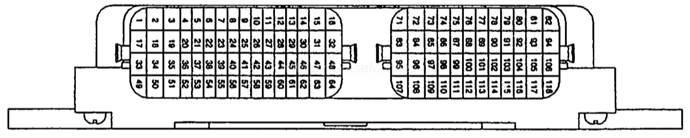
Delica D5 4B12 engine control unit input / output terminal diagram
TPS and APS
Throttle position sensor (TPS)
The throttle position sensor is mounted on the throttle body and outputs a voltage according to the rotation angle of the throttle shaft to the engine ECU. The engine ECU detects the throttle valve opening based on the voltage from the sensor and performs feedback control of the throttle control servo.

TPS mounting position
Structure and operation of TPS
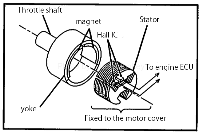
Structural diagram of TPS
From the structural diagram of TPS, it is composed of a permanent magnet fixed to the throttle shaft, a Hall IC outputting a voltage according to the magnetic flux density, a stator for efficiently guiding the speed from the permanent magnet to the Hall IC, and the like.
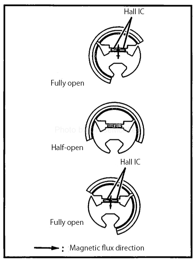
TPS operating principle diagram
According to the operation principle diagram of TPS, the magnetic flux density passing through the Hall IC and the output voltage are in a proportional relationship, and there are two systems of TPS (main) and TPS (sub), which are output to the engine ECU. Since the main and sub output voltages change as the throttle valve rotates, this allows the engine ECU to detect the actual throttle opening. (Calculate the throttle opening angle from the difference between the main and sub output voltages)
The engine ECU also compares the main and sub output voltages to check if there is any abnormality in TPS.
Accelerator pedal position sensor (APS)
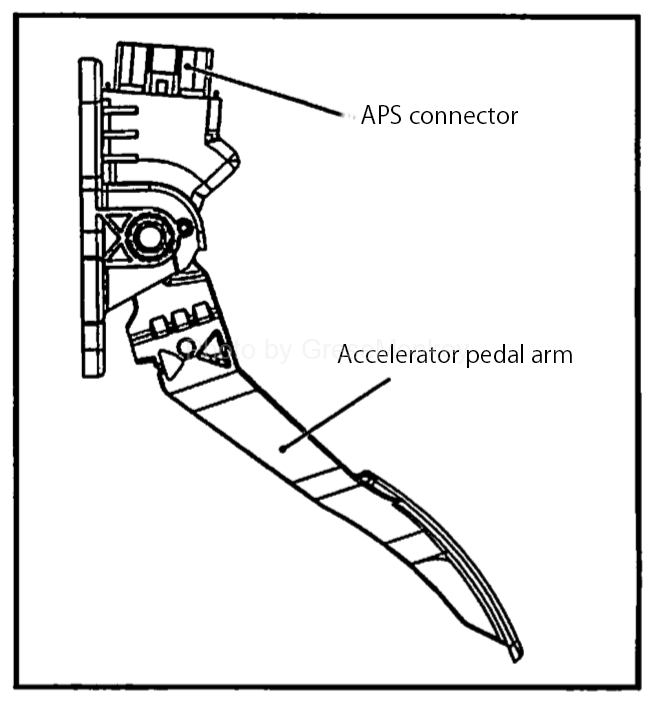
APS mounting position
It is integrated with the accelerator pedal and detects the accelerator opening. The engine ECU controls this sensor so that it has an appropriate throttle valve opening and fuel injection amount based on the output voltage of this sensor.
Structure and operation of APS
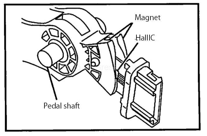
Structural diagram of APS
From the structure diagram of APS, it consists of a permanent magnet fixed to the magnet carrier of the pedal shaft, a Hall IC that outputs a voltage according to the magnetic flux density, and a stator that efficiently guides the magnetic flux from the permanent magnet to the Hall IC.
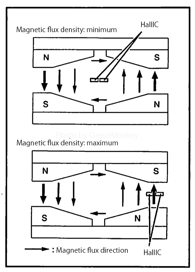
APS operating principle diagram
The magnetic flux density passing through the Hall IC and the output voltage are the same as TPS and in a proportional relationship, and the output has two systems, APS (main) and APS (sub), which are output to the engine ECU. Since the main and sub output voltages change according to the depression of the accelerator pedal, the engine ECU detects the depression amount of the pedal and the appropriate throttle valve opening degree and fuel injection amount according to the main output voltage. Control to become
Also, as with TPS, the main and sub output voltages are compared to check if there is any abnormality in the sensor.
O2 Sensorr

Structural drawing of O2 sensor
It is attached to the front and rear two places near the catalyst (catalyst) converter. And the heater is built in in order to raise temperature and activate a sensor early. As a result, air-fuel ratio feedback control can be performed in a short time immediately after startup.
Operating principle of O2 sensor
O2 sensor is an application of the principle of oxygen concentration cell of solid electrolyte (zirconia), and its output has the characteristic that it changes rapidly near the theoretical air fuel ratio. By using this to detect the oxygen concentration in the exhaust gas and feeding it back to the engine ECU, it is judged whether the air-fuel ratio is rich (rich) or lean (thin) from the theoretical air-fuel ratio. As a result, the engine ECU accurately feedback-controls the air-fuel ratio so that the purification rate of the three-way catalyst becomes the best theoretical air-fuel ratio.
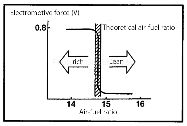
Output characteristic diagram of O2 sensor
Pressure switch
Oil pressure switch
It is mounted on the exhaust side of the cylinder block and detects oil pressure by means of a contact switch. The engine starts, the oil pressure rises, and when the pressure exceeds the specified value, the switch contact opens and the engine ECU detects the oil pressure and outputs an OFF signal to the combination meter to turn off the oil pressure warning light.
Oil pressure switch
Power steering fluid pressure switch
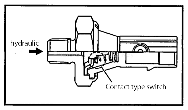
A contact switch mounted near the power steering pump detects the hydraulic pressure of the power steering.

Power steering oil pressure switch
When steering operation is performed and the power steering oil pressure increases, the switch outputs an ON signal to the engine ECU. As a result, the engine ECU keeps its idling speed stable by preventing the engine rotation from falling due to idle and power steering failure.
Role of actuator
Fuel injection control
Based on the information on voltage signals from each sensor, the engine ECU calculates and controls the fuel injection amount so that the optimum air-fuel ratio can be obtained according to the operating condition of the engine which changes according to the load and so on.
This is actually controlled by the injector drive time (injection time), and the basic drive time is determined according to the engine speed and the intake air amount as the base.
The engine ECU determines the fuel injection time in addition to the correction that is determined according to the conditions such as the intake air temperature and the engine coolant temperature during the basic drive time. Since the injection timing is performed for each cylinder, it will be once for every two engine revolutions. (Relationship between camshaft and crankshaft)