Ignition controller / igniter
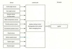
Figure 1: System diagram of the ignition control device
Ignition control in the ignition device is performed by each sensor and igniter centering on the control unit as shown in the system diagram of FIG.
The control unit determines the operating conditions of the vehicle and engine based on the signals input from each sensor, controls the optimum ignition timing and energization time for each operating condition, and then outputs an ignition instruction signal. There is.
The function of the igniter is to turn on / off the primary current of the ignition coil by the ignition instruction signal from the control unit.
Igniter
The igniter is for turning the transistor on and off to allow current to flow or cut off to the primary side in order to generate a high voltage on the secondary side of the ignition coil based on the ignition signal from the control unit. Is.
FIG. 2 shows an example of an independent ignition type igniter circuit, in which the igniter is built in the ignition coil.
As shown in the figure, the igniter has a waveform shaping circuit that molds the waveform of the signal from the control unit, an overcurrent protection circuit that prevents the primary current from exceeding a certain limit, and an overvoltage that occurs in the secondary coil does not apply to the drive circuit. It is composed of an overvoltage protection circuit, a drive circuit that sends the current controlled by these circuits to a transistor (Tr), and the like.
Igniter operation
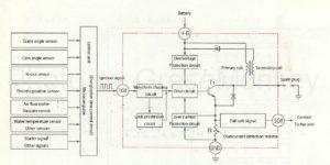
Figure 2: Independent ignition igniter circuit
In the figure, the control unit calculates the engine rotation speed and the load at that time based on the signals from the cam angle sensor, the crank angle sensor, and the like, and determines the cylinder to be ignited.
Then, after the energization time control circuit in the control unit determines the time when the primary current starts to flow through the ignition coil of the igniter, the ignition signal is sent to the igniter.
This ignition signal is sent to the drive circuit after passing through the waveform shaping circuit to drive the drive circuit.
When the drive circuit is driven, the current from the battery passes through the drive circuit through the overvoltage protection circuit and flows to the base of the transistor (Tr) to turn on the Tr.
When the Tr is turned on, the current from the battery is grounded through the primary coil, Tr, and the overcurrent detection resistor (R), so the primary current flows through the ignition coil.
Next, the ignition timing is calculated in advance by the control unit so that it becomes an appropriate ignition timing, and based on this, the control unit sends an ignition signal to the drive circuit in order to cut off the ignition signal output to the igniter. cut off.
As a result, the base current flowing from the drive circuit to the transistor (Tr) is cut off, so the Tr is turned off, the primary current is cut off, a high voltage is generated in the secondary coil, and sparks fly to the spark plug. ..
Further, when the primary current exceeds a specified value, the overcurrent protection circuit controls the base current flowing through the transistor (Tr) via the drive circuit so that no further current flows.
Overcurrent protection circuit
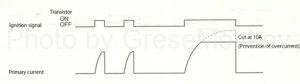
Figure 3: Relationship between ignition signal of overcurrent protection circuit and primary current
The ignition coil is integrated with the igniter, and the igniter part is smaller than the one that is not integrated. The protection circuit has a built-in overcurrent protection circuit that cuts the current only as shown in Fig. 3.
Control by control unit
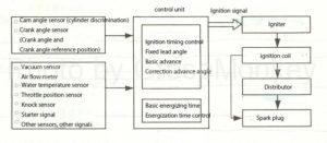
Figure 4: Ignition control by control unit
As shown in Fig. 4, the control unit calculates the position of the piston, engine rotation speed, and intake air amount (engine load) based on the signals from the crank angle sensor, vacuum sensor, air flow meter, etc., and operates at that time. An appropriate ignition timing according to the state is selected from the storage circuit, and an ignition signal is sent from the output circuit to the igniter.
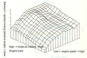
Figure 5: An example of advance characteristics
Since the storage circuit of the control unit can input the ignition timing pattern according to the engine load and the engine rotation speed in advance, it is possible to obtain a complicated advance angle characteristic as shown in FIG.
In the control by the control unit, the ignition timing control, the basic energization time and the energization time control from FIG. 4, and the comprehensive control by these will be described.
Ignition timing control
The ignition timing control has the following fixed advance angle that is controlled at the time of starting, and the advance characteristic that is obtained by adding the correction advance angle by the signal from each sensor to the basic advance angle that is controlled after the start. The advance angle is divided into the advance angle characteristics at ON (idle rotation) and OFF (normal driving) according to the idle signal from the throttle position sensor.
Therefore, the sum of the basic fixed ignition timing (without advance control) and the advance value calculated by these ignition timing controls is the ignition signal sent to the igniter, that is, the ignition timing.
Ignition timing = initial set advance angle (fixed advance angle) + basic advance angle + correction advance angle
- Control fixed advance at start (initial set advance)
Since the inlet manifold pressure is unstable at the time of starting, the ignition timing at this time is not calculated by the control unit, and a fixed value ignition signal is sent to the igniter through a dedicated circuit.
Further, the input signal from the sensor required to output as a fixed advance angle includes a signal of the crank angle sensor that detects the rotation speed at the time of starting the engine and a starter signal from the starter switch.
- Control basic advance after starting (basic advance)
The basic advance angle when the idle signal is turned on after the engine is started is controlled by a crank angle signal (rotation signal) at a preset ignition timing.
The basic advance angle when the idle signal is OFF is controlled at a preset ignition timing by a rotation signal and an inlet manifold pressure signal or an intake air amount signal.
- Control correction advance after start
After the engine is started, the engine operating state is determined from the idle signal, water temperature signal, knock signal, etc., correction values for these are calculated, and the ignition timing is controlled at a preset ignition timing.
-
- Warm-up advance correction
When the cooling water temperature is low, the ignition timing is advanced according to the operating condition to improve the operability.
-
- Idle stabilization correction
When the idle rotation speed becomes low, the ignition timing is advanced, and when it is high, the ignition timing is retarded to stabilize the idle rotation speed.
-
- Transitional correction
The ignition timing is advanced to prevent knocking when the water temperature is suddenly accelerated above 60 ° C.
-
- Acceleration correction
The operability is improved by temporarily retarding the ignition timing during acceleration.
-
- Knock correction
When the knock sensor detects knocking, the angle is retarded, and when knocking disappears, the angle is advanced. Repeat fine control to improve output and fuel efficiency.
- Maximum / minimum advance characteristics
If the ignition timing is abnormally advanced or retarded, the engine itself will be adversely affected, so the maximum and minimum evolution values are set.
Energizing time
- Basic energizing time
The control unit determines the ignition timing based on the signal from each sensor and sends the ignition signal to the igniter, but also determines the basic energization time as the time for the primary current to flow.
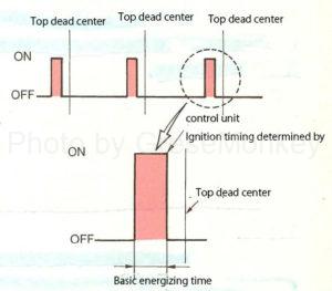
Figure 6: Ignition signal
The basic energizing time is the time when the ignition signal is ON as shown in Fig. 6, and the rise of this time is performed at a constant crank angle before the ignition timing preset in the control unit, and is turned OFF at the time of ignition. It has become like.
- Energization time control
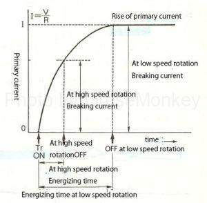
Figure 7: Rising characteristics of primary current
The magnitude of the electromotive force induced on the secondary side of the ignition coil changes depending on the magnitude of the primary current. That is, when a current is about to flow through the primary coil, a counter electromotive force is generated by the self-induction action of the coil, so that the steady current (I) is not reached until a certain time has passed as shown in FIG.
In this case, the steady-state current (I) is obtained from the battery voltage (V) and the resistance (R) of the primary circuit by Ohm’s law, and I = V / R.
The degree of rise of the primary current until it becomes a steady current is expressed by a time constant (time constant), and the smaller this value, the better the rise of the primary current.
In order to reduce the time constant, the inductance of the coil may be reduced.
When the rotation speed of the engine increases, the energizing time until the primary current flows and is cut off is short, and the engine is cut off while the current is increasing, so that the primary current decreases and the secondary induced voltage drops.
In order to prevent this decrease, it is necessary to improve the performance of the ignition coil, but it is also necessary to bring the primary current closer to the steady current. Therefore, the control unit is provided with an energization time control function to accelerate the energization time of the primary current. Therefore, it is supported by lengthening the energizing time.
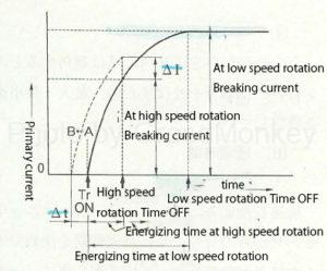
Figure 8: Energization time control
As shown in Fig. 8, if the primary current started to flow at point A, but if the current is flowed from point B, which is Δt faster at high rotation, the primary current will increase by ΔI, and the secondary voltage will increase accordingly. To do.
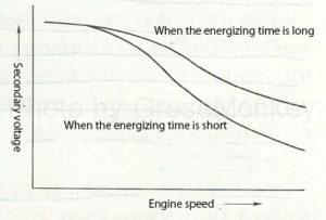
Figure 9: Relationship between energization time and secondary voltage
FIG. 9 shows how the secondary voltage of the ignition coil with respect to the engine speed changes depending on the energization time.
In particular, it can be seen that the higher the rotation speed, the greater the difference, and the longer the energization time, the higher the voltage generated.
Therefore, the energization time control advances the time when the transistor turns on (when the primary current starts to flow) as the engine speed increases.
- Time constant
The time constant is the time (seconds) from when the transistor is turned on and the primary current starts to flow until the current value becomes 0.632 times the steady current.
- Inductance
When the current of the circuit is changed, an electromotive force is generated by the electromagnetic induction action. The ratio of the electromotive force to the change of the current at this time is called inductance or induction coefficient, and it changes in proportion to the square of the number of turns of the coil. The unit is Henry (H).
Comprehensive control
For comprehensive control, using Fig. 10 as an example, the detection condition of the reference signal is set to 10 ° per cycle of the crank angle reference position signal of the cam angle sensor, and the basic ignition timing is determined based on the two signals. It is explained as.
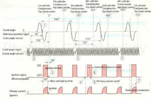
Figure 10: An example of comprehensive control for a 6-cylinder engine
Since the ignition timing is usually determined as many times before the piston compression top dead center in anticipation of the combustion time at which the combustion pressure is maximized, in order to send an ignition signal to each cylinder according to the firing order at an appropriate time. Needs to detect (cylinder discrimination) the compression top dead center of the reference cylinder (first cylinder), and for that detection, the control unit calculates the relative positions of the cam angle sensor and the crank angle sensor. It is done by doing.
Since the crank angle sensor signal rotor has a missing tooth part, the crank angle signal changes as shown in part (2) in the figure, but the position delayed by 150 ° from the center of that part is the first cylinder or It is detected as the compression top dead center of the 6th cylinder.
On the other hand, these cylinder discriminations are performed by the crank angle reference position signal (cam angle sensor), and the reference position signal closer to the part (2) in the figure, that is, the reference signal in (1) in the figure delayed by 90 ° is the first. It is recognized as the signal of the first cylinder. Therefore, the ignition timing is determined to be 15 ° before the compression top dead center of the first cylinder (③ in the figure).
Then, the control unit controls the ignition signal to be turned on 35 ° before the basic energization time required from this ignition timing. Then, an ignition signal as shown at the bottom of the figure is output to the igniter.
Figure 10: An example of comprehensive control for a 6-cylinder engine
Next, when the engine rotation speed increases, the primary current decreases, so the energization start time should be shortened (④ in the figure) based on the energization time control circuit by the crank angle signal (rotation signal). Along with the control, the correction advance angle of the control unit is added (⑥ in the figure), and the cutoff time of the primary current of the igniter is shortened accordingly. (⑤ in the figure)
In addition, the overcurrent protection circuit of the igniter controls the current value so that it does not exceed the specified current value so that an excessive primary current does not flow. (⑦ in the figure)
Further, the factors that determine the ignition timing include the engine rotation speed and the engine load (inlet manifold pressure). The engine rotation speed is calculated by the control unit based on the number of crank angle signals generated in a certain period. The state of the engine load is detected by obtaining the intake air amount per engine speed with a vacuum sensor or an air flow meter.
As described above, the electronically controlled ignition device selects the ignition timing suitable for the operating state of the engine and secures a stable ignition spark.