Gasoline engine body structure
Gasoline engine The engine body burns a mixture of gasoline and air in a combustion chamber, converts the pressure energy of the generated combustion gas into rotational energy, and generates power.
There are 4 cycle and 2 cycle reciprocating type (reciprocating engine) and rotary type rotary engines, and there are series type, V type, horizontally opposed type, etc. depending on the arrangement of cylinders.
Table of Contents
- Engine format
- Cylinder head
- Cylinders and cylinder blocks
- Piston
- Piston ring
- Connecting Rod/Connecting Rod Bearing
- Crankshaft
- Journal Bearing
- Force acting on the crankshaft
- Balancer mechanism
- Flywheel/Ring Gear
- Valve mechanism
- Timing Belt Chain
Engine format
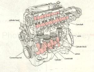
Figure 1: Reciprocating engine (DOHC type 4-cycle in-line 4-cylinder)
Figure 1 shows an example of a DOHC (double overhead camshaft) 4-cycle in-line 4-cylinder reciprocating engine.
The engine body is composed of a cylinder head, a cylinder block, a cylinder, a piston, a connecting rod, a crankshaft, a camshaft, a valve and the like.
In addition, the engine body is provided with passages such as a lubrication device, a cooling device, and an intake / exhaust device, which are also a base for mounting each auxiliary machine.
- In-line engine (reciprocating engine)
The in-line engine is the most common type of cylinder as shown in Fig. 1. Generally, the number of cylinders is 3 cylinders (mostly in light vehicles), 4 cylinders, or 6 cylinders.
- V-type engine
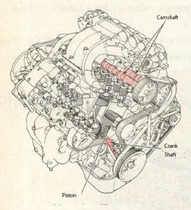
Figure 2: V-type engine
As shown in Fig. 2, the V-type engine has cylinders arranged in a V-shape centered on the crankshaft, and the overall length of the engine body can be shortened compared to the in-line type.
- Horizontally opposed engine
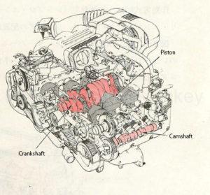
Figure 3: Horizontally opposed engine
As shown in Fig. 3, the horizontally opposed engine has cylinders arranged horizontally facing each other with the crankshaft at the center. Compared to the in-line type, the overall length of the engine body can be shortened like the V type. Furthermore, because it is a horizontal type, the height of the engine can be lowered.
- Rotary engine
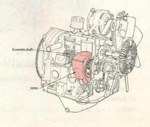
Figure 4: Rotary engine
As shown in Fig. 4, the rotary engine has a conical rotor arranged in the axial direction of the eccentric shaft (output shaft). Unlike the reciprocating engine, which converts the reciprocating motion of the piston into the rotational motion of the crankshaft, the rotational motion of the rotor is directly converted into the rotational motion of the eccentric shaft (output shaft), so transmission loss is small.
cylinder head
The cylinder head forms a part of the combustion chamber as shown in Fig. 5, and a water jacket for passing cooling water is provided inside the cylinder head, and an inlet manifold, an exhaust manifold, a valve mechanism, and a spark plug are provided outside the cylinder head. Etc. are attached.
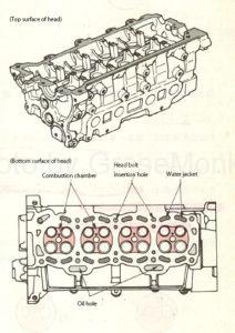
Figure 5: Cylinder head
Since the cylinder head is constantly exposed to high temperature and high pressure, it is required to have high thermal conductivity and cooling efficiency. Therefore, a cylinder head made of an aluminum alloy is generally used.
Combustion chamber
The combustion chamber is composed of a cylinder head, a piston, and the like, and its shape differs depending on many factors such as the position of the valve and spark plug, the shape of the upper surface of the piston, and the like, and has a great influence on the engine output and the generation of exhaust gas.
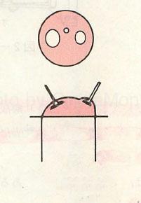
- Wedge type (wedge type)
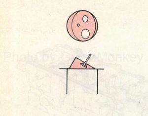
The wedge type combustion chamber has a shape as shown in FIG. 6, and since the air-fuel mixture at the tip of the wedge is pushed out by the piston during compression, a vortex is given to the air-fuel mixture in the combustion chamber.
- Bathtub type (bathtub type)
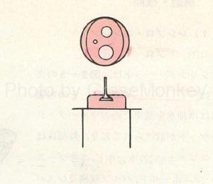
As shown in Fig. 7, the bathtub type combustion chamber has the inlet and exhaust valve recessed, and the cylinder head structure is simple.
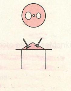
- Hemispherical
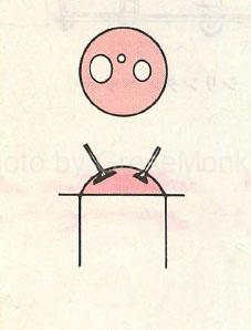
The hemispherical combustion chamber has a shape as shown in FIG. 8, and the size of the inlet and the exhaust valve can be increased, but the valve opening / closing mechanism is more complicated than that of the wedge type or the bathtub type.
- Multi-sphere type
The multi-spherical combustion chamber has a shape that forms a plurality of spheres as shown in FIG. 9, and the valve can be enlarged to give a vortex to the mixer.
- Vent roof type (roof type)
The roof-type combustion chamber has a shape as shown in FIG. 10, and is a type in which a roof-type combustion chamber is formed on the inlet and exhaust valve surfaces and the piston head surface which are arranged facing each other on the left and right sides.
Squish area
Most of the combustion shapes are roof-shaped, but various improvements have been made to make the combustion chamber smaller to increase the compression pressure, and to provide a squish area in the combustion chamber to generate a vortex in the air-fuel mixture. There is.
The squish area refers to a gap (gap) formed between the bottom surface of the cylinder head and the top surface of the piston, and the flow velocity of the vortex of the air-fuel mixture generated by this squish area is the area of the squish area and its thickness (the squish area). It is greatly affected by the clearance), and the larger the area and the smaller the thickness, the higher the value.
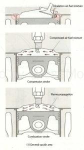
Figure 10-(1): Squish area
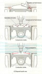
Figure 10-(2): Squish area
The squish area should be as small as possible between the piston head and the inner surface of the cylinder head as shown in Fig. 10-2 (1), and when the piston approaches top dead center, the air-fuel mixture is pushed out from that part and the flow velocity is increased. A vortex is generated by concentrating in the direction of the spark plug.
Also. The diagonal squish area in Fig. 10-2 (2) is a further development of Fig. 10-2 (1), and the oblique shape allows smooth intake from the suction passage, resulting in the generation of a stronger eddy current.
In this way, the vortex flow in the squish area plays a role of suppressing an increase in the maximum combustion gas temperature by increasing the speed of flame propagation in the combustion stroke and shortening the combustion time of the mixer. (Reduction of NOx)
Cylinder head intake / exhaust system
The cylinder head is provided with an intake passage for the mixer and an exhaust passage for the burned gas.
The suction passage (inlet manifold) has a shape in consideration of a flow for increasing the filling efficiency of the air-fuel mixture and increasing the combustion efficiency in the combustion chamber.
Further, the exhaust passage (exhaust manifold) is shaped so as to increase the exhaust efficiency of the burned gas.
Cylinder head cooling system
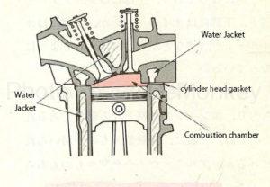
Figure 11: Cylinder head shape
As shown in FIG. 11, the cylinder head is provided with a water jacket for cooling the combustion chamber and the valve seat portion on the outer periphery of the combustion chamber.
Cylinder head gasket
The cylinder head gasket prevents leakage of combustion gas, cooling water, engine oil, etc., and is assembled between the cylinder block and the cylinder head.
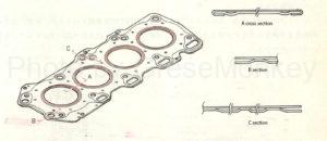
Figure 12: Cylinder head gasket
In addition, since the cylinder head gasket is required to have heat resistance, pressure resistance, and appropriate compressibility, generally one mild steel plate or a combination of two mild steel plates as shown in Fig. 12 is used. It is used, and the surface is coated with fluorine-based rubber as a sealing agent to improve adhesion. In addition, asbestos (asbestos) or graphite (graphite) is filled with herring and the cylinder bore and the oil hole are wrapped with mild steel plate.
- Steel gasket
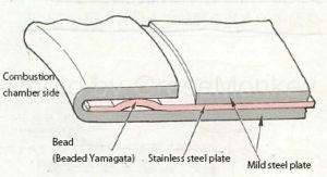
Figure 12-1: Steel gasket
As shown in Fig. 12-1, the steel gasket has a structure in which several mild steel plates and stainless steel plates are laminated, and the seal portion is bead-shaped (bead-shaped chevron shape with a spring effect) in order to improve compressibility.
- Composite gasket
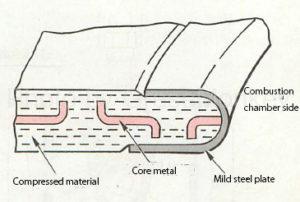
Figure 12-2: Composite gasket
As shown in Fig. 12-2, the composite gasket has a structure in which a compression material using expanded black smoke is filled with metal and wrapped in mild steel plate, and has excellent heat resistance and adhesion.
In addition, there are also those using special fibers (aramid-based fibers, phenol-based fibers, etc.) as the compression material.
Cylinder and cylinder block
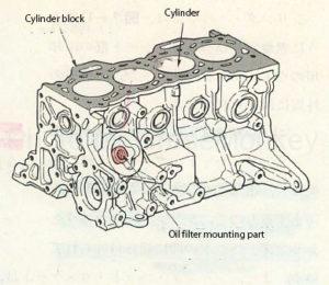
Figure 13: Cylinder block
Cylinder
The cylinder is cast integrally with the cylinder block, and there is also a type in which a cylinder liner is press-fitted in order to improve wear resistance.
The cylinder is a part where the piston reciprocates, and forms a combustion chamber together with the piston and the cylinder head. It also works to dissipate the heat of the cylinder wall due to combustion to the cooling water inside the water jacket.
Cylinder block
As shown in Fig. 13, the cylinder block has a cylinder inside to support the piston, crankshaft, etc., and is also the base for mounting each engine accessory. The cylinder head is on the top and the oil pan is on the bottom. An oil filter etc. is attached to the side part.
In addition, a passage for cooling water and engine oil is also provided, which is a part that becomes the skeleton of the engine.
The material of the cylinder block is generally an aluminum alloy, but some are made of cast iron.
piston
The piston has a structure as shown in Fig. 14- (1), is connected to the connecting rod via the piston pin as shown in Fig. 14- (2), reciprocates in the cylinder, and the volume changes in the cylinder. To form.
The pressure generated by combustion in this airtight chamber is received by the piston, which powers the piston to rotate the crankshaft via the connecting rod.
Since the piston is constantly exposed to high temperature and high pressure and reciprocates in the cylinder, light weight, toughness, heat resistance and wear resistance are required. Therefore, the material is generally a highly durable aluminum alloy. Is used.
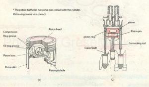
Figure 14: Piston structure and assembly condition
Aluminum alloy pistons are lightweight and have high thermal conductivity, so they are suitable for high-speed reciprocating motion, but because of their large coefficient of thermal expansion, various shapes and structures have been devised.
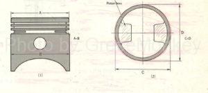
Figure 15: Aluminum alloy piston
As shown in FIG. 15, when the piston is viewed from the side when the piston is cooled, the diameter of the skirt portion is large, and the closer to the piston head, the smaller the diameter, and the overall shape is conical. This is because the degree of expansion is large when the piston works and the head is heated. When the engine is functioning and the piston is moving up and down, this thermal expansion causes the piston to expand to a size that keeps the cylinder, piston, and combustion chamber confidential.
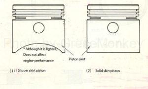
Figure 16: Types by piston skirt
Further, in order to reduce the mass of the piston itself, a skirt portion in the boss direction is generally cut out as shown in FIG. 16 (1). This notch is called a slipper skirt piston, and the one not notched as shown in Fig. 16 (2) is called a solid skirt piston.
In addition to this, there are those in which the piston head is dented to provide relief for the inlet and exhaust valve, and those in which the head is projected to increase the compression ratio.
Piston pin
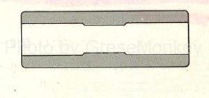
Figure 17: Cross section of piston pin
The piston pin is a hollow cylindrical shape that connects the piston and the small end of the connecting rod, and is made thicker by reinforcing the central part as shown in FIG. 17 in order to receive a large force from the piston.
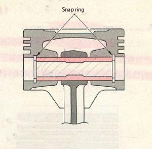
Figure 18: Piston pin mounting condition
In addition, as shown in Fig. 18, the piston pin can rotate freely without being fixed to the connecting rod or the piston boss, so the grooves at both ends of the piston boss prevent the piston pin from coming off. A snap ring is attached to.
The piston pin is made of special steel, and its surface is hardened by charcoal burning to give it toughness and wear resistance.
Various ideas for pistons
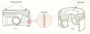
Figure 18-1: Piston
Since the piston reciprocates at high speed under high temperature and high pressure, it is required to have excellent thermal conductivity and wear resistance, small thermal expansion, and light weight. Therefore, an aluminum alloy containing copper, silicon, nickel, or the like is used as the material.
As for the aluminum alloy piston, the one having a high silicon content is called a high silicon aluminum alloy piston, and the one having a lower silicon content is called a low X piston.
In addition, the piston has been devised in various ways as described below.
- In order to reduce the mass of the piston, the distance from the piston head to the top ring groove is shortened, and the piston skirt is shortened.
- The piston skirt is finished with streaks, and resin coating or tin plating is applied to improve engine oil retention, improving initial familiarity, preventing piston seizure, and reducing noise and friction.
- A diagonal squish area is provided on the piston head to generate a vortex of the air-fuel mixture.
- A valve relief is provided on the piston head to increase the compression pressure.
Force acting on the piston
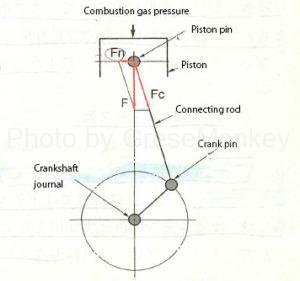
Figure 18-2: Force acting on the piston
On the piston, the force (F) of the combustion gas pressure applied to the piston head and the inertial force of the reciprocating part acts in the direction of the arrow in Fig. 18-2.
But Since the connecting rod is tilted, this force (F) is divided by a vector into Fc in the connecting rod direction and Fn in the direction perpendicular to F.
Fn is called side thrust and causes piston striking noise (slap noise) and uneven cylinder wear.
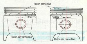
Figure 18-3: Offset piston
As shown in Fig. 18-3, some pistons use a piston in which the center position of the piston pin is slightly offset to the left and right with respect to the center of the piston to prevent the piston from hitting the sound. (Offset piston)
piston ring
There are two types of piston rings, a compression ring and an oil ring. Generally, two compression rings and one oil ring are attached to the piston, and the piston ring itself comes into close contact with the cylinder due to its own tension. There is.
Special cast iron and carbon steel are used as the material of the piston ring from the viewpoint of heat resistance and wear resistance, and some of them are surface-treated such as chrome plating to improve wear resistance. is there.

Figure 19: Piston ring name
Compression ring
The compression ring keeps the combustion chamber confidential, prevents compression leaks and gas leaks, and allows most of the heat received by the piston to escape through the cylinder to the cooling water of the water jacket.
The types of compression rings are as follows, but generally, a barrel face type and a tapered face type are used. In addition, some use a combination of the two.
- Plain type
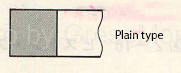
It is the most basic shape and has excellent airtightness and thermal conductivity.
- Barrel face type
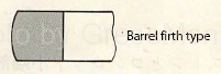
Since the sliding surface has an arcuate shape, it has the feature of preventing abnormal wear during initial familiarization, and is often used for top rings.
- Tapered face type
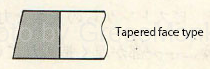
Since the sliding surface is tapered, it easily fits into the cylinder wall as a line contact, and has excellent oil-scraping performance and airtightness, and is generally used for the second ring.
- Inner bevel type
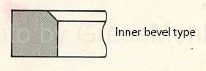
It is commonly used for top rings or second rings due to its ability to scrape oil.
- Undercut type and taper undercut type
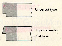
Since it plays a role in preventing oil from rising, it is often used as a second ring just above the oil ring.
- Action during inhalation stroke
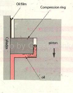
Figure 21: Inhalation stroke
In the suction stroke, as shown in FIG. 21, the oil on the cylinder wall is scraped off by the piston skirt and the oil ring as the piston descends, and the compression ring scrapes off the remaining oil. However, a small amount of oil that could not be scraped off still forms an oil film on the cylinder wall to prepare for lubrication during the next compression stroke.
Further, since the pressure at the upper part of the piston is lower than that inside the crankcase, the engine oil flows from the gap on the lower surface of the ring to the inside of the ring as shown in FIG.
Therefore, at this time, if the ring or cylinder is worn or the ring is damaged, the oil rises and the oil consumption increases.
- Actions during compression and combustion strokes
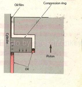
Figure 22: Compression stroke
In the compression stroke, as shown in FIG. 22, the compression pressure in the cylinder acts on the upper surface and the inner surface of the ring, so that the compression ring is strongly pressed against the lower surface of the ring groove and the cylinder wall. The momentary time between burning is even stronger.
Therefore, if the ring, cylinder, or the like is worn, airtightness cannot be maintained, which causes an increase in blow-by gas and insufficient output.
- Action during exhaust stroke
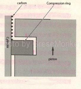
Figure 23: Exhaust stroke
In the exhaust stroke, as shown in FIG. 23, the compression ring removes carbon and the like due to combustion adhering to the cylinder wall and pushes the cylinder upward, so that carbon is discharged from the exhaust valve together with the combustion gas.
Oil ring
The oil ring plays a role of scraping off excess oil that lubricates the inner wall of the cylinder, and generally, a combination type oil ring that combines a side rail and a spacer expander as shown in FIG. 24 is used.
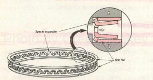
Figure 24: Combination oil ring
The spacer expander increases the area of the engine oil escape portion to prevent the oil from being scraped off due to the accumulation of carbon and the like, so the oil writing performance is superior to other rings.
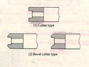
Figure 25: Types of oil rings
In addition, there are other types of oil rings as shown in Fig. 25.
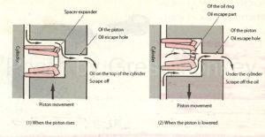
Figure 26: Action of oil ring
The action of the oil ring is to scrape off excess oil that lubricates the inner surface of the cylinder, and when the piston rises, it pushes the oil inside the piston through the oil relief hole provided in the piston as shown in Fig. 26 (1). Further, when the piston is lowered, as shown in FIG. 26 (2), the scraped oil is pushed out to the inside of the piston through the oil relief portion provided in the ring itself and the oil relief hole of the piston.
Abnormal phenomenon that occurs in the piston ring
Piston rings, like pistons, are exposed to high temperature, high pressure combustion gases. Further, since the reciprocating motion in the cylinder is performed at high speed, the following phenomena occur under various forces.
- Scuff phenomenon
The scuffing phenomenon means that the oil film on the cylinder wall breaks and the ring and the cylinder wall come into direct contact with each other, resulting in scratches on the surface of the ring or cylinder. It is likely to occur when overheating occurs.
- Stick phenomenon
The stick phenomenon means that carbon and sludge (combustion products) solidify and the link does not move. As a result, airtightness and oil scraping performance deteriorate, and oil rises and output decreases.
- Flutter phenomenon
The flutter phenomenon is a phenomenon in which the piston ring floats up without being in close contact with the ring groove. Occurs when the force is exceeded.
This phenomenon is more likely to occur when the compression ring or cylinder wall is worn, and this phenomenon is more likely to occur as the expansion force of the piston ring is smaller, the width of the piston ring is wider, and the piston speed is faster.
Therefore, when this phenomenon occurs, the function of the piston ring is impaired, the engine output is insufficient due to gas leakage, the oil consumption is increased, and abnormal wear of the ring groove and the upper and lower surfaces of the ring is promoted.
In the normal case, the compression ring is strongly pressed against the cylinder wall by the expansion force peculiar to the ring and the pressure acting on the inner peripheral surface of the ring.
Connecting rod / connecting rod bearing
Connecting rod
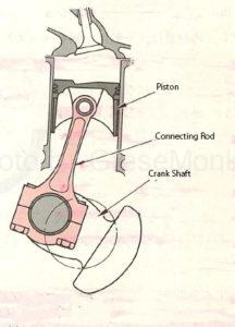
Figure 27: The role of the connecting rod
The connecting rod connects the piston and the crankshaft as shown in FIG. 27, and plays a role of converting the reciprocating motion of the piston into the rotational motion of the crankshaft.
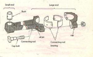
Figure 28: Horizontal split connecting rod
The connecting rod has a structure as shown in Fig. 28, and is made of special steel so that it can withstand a large impact force repeatedly, and its cross section is forged into an I shape.
A piston is connected to the small end of the connecting rod via a piston pin, and some use a bush and some do not.
The large end of the connecting rod is generally a horizontally split type as shown in FIG. 28, and is attached to the crank pin with a cap bolt via a connecting rod bearing. The cap bolt is made of special steel to withstand the large impact force in the pulling direction, which is used for the positioning of the cap.
Further, as shown in FIG. 28, an oil jet for cooling the piston and for lubricating the piston pin, the piston and the cylinder is generally provided on the large end shoulder of the connecting rod.
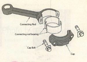
Figure 29: Diagonally split connecting rod
In addition to the horizontal split type, the large end of the connecting rod is also a diagonal split type as shown in Fig. 29. This is because when the pin diameter of the crankshaft becomes large, the shape of the large end part becomes large in the horizontal division type, the shoulder part of the connecting rod hits the lower surface of the cylinder at the time of disassembly, and the connecting rod cannot be pulled out to the upper part of the cylinder. The formula makes it easy to disassemble and assemble the engine.
Bush at the small end of the connecting rod
The material of the bush is generally made of a copper-based alloy, and an oil hole is made to match the oil hole at the small end of the connecting rod, and the oil that is blown into the piston is discharged from there. It is supposed to be supplied.
Connecting rod bearing
- Trimetal
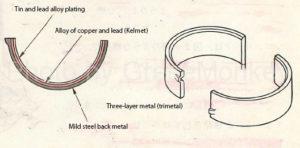
Figure 30: Trimetal
Trimetal (three-layer metal) is made by sintering an alloy (Kelmet metal) made by adding 20 to 30% lead to copper onto a rigid backing metal, and then plating an alloy of lead and tin or an alloy of lead and indium on it. By taking advantage of the mechanical strength (fatigue resistance, impact resistance, etc.) of Kelmet metal, its drawbacks such as familiarity and poor burial property can be solved by using an alloy of lead and tin or an alloy of lead and indium. It is a supplement.
- Aluminum alloy metal
It is an alloy of aluminum with 10 to 20% tin added. It has excellent corrosion resistance and fatigue resistance, has a high allowable temperature, and the width of the metal is about 20% narrower than other metals.
Those with a high tin content have excellent wear resistance, but have a large coefficient of thermal expansion, so it is necessary to take a large oil clearance. In addition, some aluminum alloy metals have a little less than 10% lead added to aluminum in order to further improve the compatibility and corrosion resistance.
Connecting rod bearing elements
- Thick
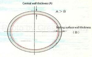
Figure 30-1: Connecting rod bearing wall thickness
As shown in Fig. 30-1, the wall thickness of the connecting rod bearing is generally made thinner in the mating surface (horizontal direction) with respect to the wall thickness in the central portion (vertical direction). This is because the force applied to the bearing is large in the vertical direction, and the clearance in the vertical direction cannot be increased so much to prevent hitting noise due to impact. For reasons such as better assembly with the shaft.
- Crash height
The crash height is the tightening allowance of the bearing, and means the difference between the outer peripheral dimension of the bearing and the inner circumference of the bearing housing, that is, the tightening allowance of the bearing.
If the crash height is too large, the bearing will bend and a local load will be applied, causing premature fatigue and breakage of the bearing. (Because the gap between the bearing and the housing is too large)
On the contrary, if the crash height is too small, even if the cap bolt of the connecting rod is tightened, the adhesion between the bearing housing and the back metal of the bearing body becomes poor, and heat conduction becomes poor, which causes seizure.
- Bearing tension
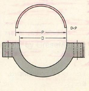
Bearing tension means that the free-state dimension (P) of the bearing is larger than the bearing housing diameter (D), as shown in FIG. This difference in size is called tension, and is for improving the adhesion to the housing when the bearing is assembled.
Properties required for connecting rod bearings
- Non-burn-in
When metal contact occurs between the bearing and the crankshaft pin, the bearing does not easily seize.
- Familiarity
When the bearing is attached to the crankshaft pin, it has the property of immediately adapting to the crankshaft pin even if the contact is somewhat bad at first.
- Burial
It refers to the property of embedding foreign matter on the surface of the bearing. Therefore, a bearing with good burial property is less likely to damage the shaft.
- Corrosion resistance
Corrosion resistance is the property that is not easily corroded by acids. Engine oil participates in blow-by gas and the like, and oxidation products increase. These adhere to the bearings and cause corrosion. Especially at high temperatures.
- Fatigue resistance
It refers to the property that the mechanical properties of bearings do not change easily even when a load is repeatedly applied to the bearings, and fatigue resistance is important when the direction of force changes, such as in connecting rod bearings.
Crankshaft
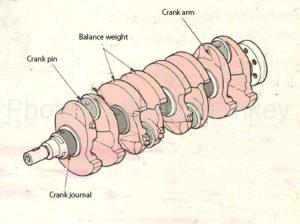
Figure 32: Crankshaft
The crankshaft is for changing to a rotary motion through the reciprocating motion of the piston, and is composed of a crank pin, a crank journal, a crank arm, a balance weight and the like as shown in FIG. 32.
The balance weight is the mass of the rotating part.
It is provided on the crank arm to remove the imbalance.
Generally, the number of crank journals is 5 for 4 cylinders, 7 for 6 cylinders, 4 for V type, 5 for 8 cylinder V type, and crankshaft. Is supported by the cylinder block in this journal section. That is, the crank journals are arranged side by side in the axial direction of the crankshaft.
Also, the number of crank pins is generally the same as the number of cylinders, but some V-types have half the number of cylinders because two connecting rods are attached to one crank pin. ..
Special steel, carbon steel, special cast iron, etc. are used as the material of the crankshaft, and the crank journal and the crank pin portion are induction hardened to increase the surface strength to improve the wear resistance.
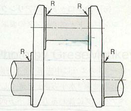
In order to eliminate imbalance with respect to the axis of the crankshaft, holes are made in the balance weight, the mass of the weight is adjusted, and the crankpin and the end (R) of the journal are as shown in Fig. 32-1. , Rounded to avoid concentration of force.
In addition, in the cast one, the pin and the journal portion have a hollow structure to reduce the weight.
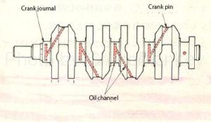
Figure 33: Crankshaft oil passage
Further, as shown in FIG. 33, an oil passage connecting the crank journal and the pin is provided to supply oil to the crank pin and the connecting rod bearing.
A crankshaft timing gear for operating the valve mechanism, etc., and a crank pulley for driving a water pump, alternator, etc. are attached to the front end of the crankshaft, and a flywheel or drive plate is attached to the rear end. Has been done.
In many cases, a pilot bearing of the clutch shaft is attached to the rear end.
Journal bearing
As for the journal bearing, an insert type trimetal is generally used like the connecting rod bearing, and the journal bearing is fitted in the cylinder block and the bearing cap, respectively. The width of the journal bearing may vary depending on the mounting position, and an oil hole and an oil groove are provided on the inner surface so that the oil pumped from the cylinder block is sufficiently filled between the crank journal and the bearing.
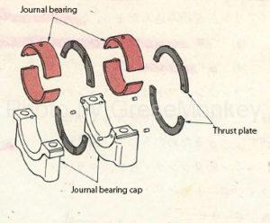
Figure 34: Journal bearings and thrust plates
In addition, a thrust bearing is provided in one place of the journal to receive an axial force of the crankshaft. Some are integrated with journal bearings and others are separately attached as thrust plates as shown in Figure 34.
Force acting on the crankshaft
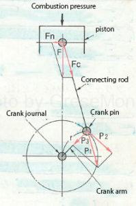
Figure 34-1: Force acting on the crankshaft
As shown in Fig. 34-1, the force (F) that pushes the piston downward is divided into Fn and Fc by vector decomposition, and Fc is transmitted as the force of the crank pin P1 via the connecting rod.
The force of P1 is divided into the force in the direction of rotation of the crankpin (P2) and the force in the direction of the crank journal (P3). The shaft torque is the product of the turning radius (r) of.

Figure 34-2: Tortional damper
Further, the crankshaft causes torsional vibration due to fluctuations in torque due to combustion pressure. In order to absorb this torsional vibration, a torsional damper is provided on the crank pulley at the front end of the crankshaft as shown in Fig. 34-2.
The action of the torsional damper is as follows.
When the crankshaft maintains a constant rotation speed, the pulley portion rotates integrally with the crankshaft.
When the crankshaft undergoes torsional vibration (large positive or negative acceleration with respect to the direction of rotation), the pulley section tries to continue rotating at a constant speed, causing the intermediate rubber to deform, which causes torsion. Performs vibration damping action.
Balancer mechanism
In addition to the above, the forces acting on the crankshaft include the inertial force of the reciprocating part and the centrifugal force of the rotational movement part, but these are not effective forces and cause noise and vibration. In order to suppress this vibration, some engines are provided with a balancer mechanism.
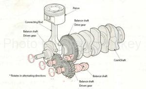
Figure 34-3: Balancer mechanism
Figure 34-3 shows an example of a balancer mechanism, which consists of two balance shafts, a balance shaft drive gear that drives them, and a balance shaft driven gear.
The balance shaft rotates twice as fast as the crankshaft in the direction of the arrow shown in Fig. 34-3.
The vibration source of the engine is the inertial force of the reciprocating part generated when the piston or connecting rod reciprocates. As a method of reducing this inertial force, a balance weight is provided on the crankshaft, thereby reducing the primary inertial force (one cycle of inertial force is generated for one rotation of the engine).
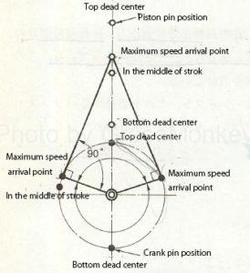
Figure 34-4: Piston maximum speed reach
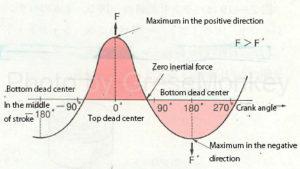
Figure 34-5: Inertial force of the piston
However, as shown in Fig. 34-4, the maximum speed of the piston is closer to the top dead point than the middle of the stroke, so the inertial force generated during one cycle is in the positive direction of the piston as shown in Fig. 34-5. The inertial force (F) and the negative inertial force (F’) are not exactly the same, and the positive inertial force (F) is larger than the negative direction.
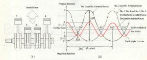
Figure 34-6: Secondary inertial force
In an engine in which the 1st and 4th pistons are in the same layer as shown in Fig. 34-6 (1), the 2nd and 3rd pistons are 180 ° out of phase and in phase.
Therefore, these inertial forces are the same as the above-mentioned inertial forces as shown in Fig. 34-6 (2), but in the resultant force of the inertial forces Nos. 1 to 4, the resultant force (A) at point a is 1. The difference between the positive inertial force (F) of No. 4 and the negative inertial force (F’) of No. 2 and 3, that is, F-F’= A, and the resultant force (B) of point b is , No. 1 and No. 4 negative inertial force (f) and No. 2 and No. 3 negative inertial force (f) add up to f + f = B.
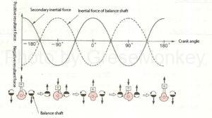
Figure 34-7: Damping action of secondary inertial force by balance shaft
The resultant force of this inertial force (red line in the graph in Fig. 34-6 (2)) is called the secondary inertial force and is represented by the solid line in Fig. 34-7, which is 2 per rotation (360 °) of the engine. Since the inertial force of the cycle is generated, the inertial force cannot be reduced by the balance weight.
Therefore, a balance shaft that rotates at twice the rotation speed of the engine is provided to generate an inertial force of opposite phase as shown in Fig. 34-7 to cancel the secondary inertial force.
Flywheel / ring gear
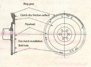
Figure 35: Flywheel
The flywheel is as shown in Fig. 35. In a 4-cycle engine, it has the function of changing the rotational force that changes due to combustion every 2 revolutions, and in a 2-cycle engine, it has the function of transmitting power from the crankshaft to the clutch. I’m playing.
That is, when the rotational force of the crankshaft increases due to the combustion stroke, the flywheel absorbs the energy, and when the rotational force of the crankshaft decreases in the stroke other than combustion, the flywheel itself rotates. It is maintained to reduce the change in the rotational speed of the crankshaft and maintain a smooth rotational state.
The flywheel is made of cast iron and is attached to the rear end of the crankshaft. In addition, the ring gear is for engaging the starter and pinion when starting the engine and transmitting the rotation of the starter to the flywheel. Generally, a carbon steel spur gear is used and is shrink-fitted on the outer circumference of the flywheel. ing.
The size of the flywheel depends on the engine output, rotational speed and number of cylinders, but it has a fairly large diameter and mass and is provided with bolt holes for mounting the crankshaft and clutch.
In addition, the friction surface with the clutch disc is finished smoothly.
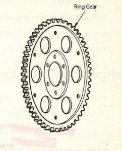
Figure 36: Drive plate
In an engine equipped with a torque converter, a flywheel is not provided because the torque converter acts as a flywheel. Therefore, a lightweight and thin drive plate as shown in Fig. 36 is attached to the rear end of the crankshaft.
Valve mechanism
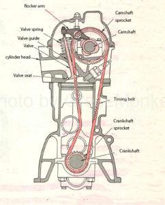
Figure 37: Valve mechanism
The valve opens and closes the combustion chamber directly, is exposed to high temperature and high pressure, and repeatedly impacts with the valve seat, so it is made of special steel with high heat resistance and wear resistance.
The valve includes an inlet valve that introduces the air-fuel mixture into the combustion chamber and an exhaust valve that discharges combustion gas from the combustion chamber.
Generally, the outer diameter of the inlet valve head is larger than that of the exhaust valve in order to increase the intake air-fuel mixture amount, and these valves are opened and closed by the cam of the camshaft.
valve
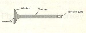
Figure 38: Name of each part of the valve
The valve has a structure as shown in Fig. 38, is inserted into a special cast iron valve guide press-fitted into the cylinder head as shown in Fig. 39, and an upper spring seat is fixed to the upper end of the valve stem with a cotter in half. Has been done.
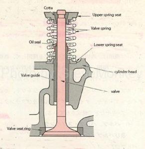
Figure 39: Valve mounting condition
Further, in order to prevent the oil from falling into the combustion chamber, a heat-resistant and oil-resistant oil seal is attached to the tip of the valve guide.
Since the valve is exposed to a high temperature during operation, it is required to have excellent thermal conductivity, heat resistance, corrosion resistance, wear resistance and impact resistance.
Conventionally, there was one inlet valve and one exhaust valve per cylinder, two inlets and one exhaust, but four valves per cylinder were provided to improve the intake and exhaust rate. The mainstream is to improve the performance of the engine.
Inlet valve
Since corrosion resistance at low temperatures is important for inlet valves, special steel containing carbon steel containing silicon and chromium is used as the material. In particular, it has excellent corrosion resistance and “thermal conductivity”. It has features such as “good”, “small coefficient of thermal expansion”, and “sufficient altitude can be obtained”. In addition, the surface is hardened to improve wear resistance.
Exhaust valve
Since the exhaust valve is exposed to high temperatures, heat resistance is important. Therefore, special steel containing carbon steel containing chromium and nickel is used as the material. In addition, it has excellent heat resistance. It is also highly resistant to corrosion.
For the exhaust valve, the valve head is made of a material with excellent heat resistance, and the valve stem is made of a material with excellent wear resistance. There is also an improved version.
Some valve faces and valve stem ends are plated with Stellite, which has excellent wear resistance.
Valve spring
Figure 39: Valve mounting condition
The valve spring is for closing the valve and is attached with a lower spring seat, an upper spring seat and a cotter.
In addition, in order to prevent abnormal vibration of the valve during high-speed operation, use an unequal pitch spring with a narrow pitch on the cylinder head side, and to improve the adhesion between the valve face and valve seat, and to prevent abnormal valve vibration at high speed. To prevent this, some use double double springs inside and outside as shown in Fig. 39.
Heat resistant spring steel is used as the material of the valve spring.
Valve spring surging
The valve spring cannot open and close the valve accurately unless the load during operation is higher than the inertial force acting on the reciprocating part. If this operating load is lower than the inertial force acting on the reciprocating part, the valve will move away from the cam or dance when seated on the valve seat.
When one end of the valve spring is suddenly compressed, each coil of the spring is sequentially compressed from the compressed end, which is reflected by the other end and becomes a compression wave that reciprocates in the coil at a constant cycle. When this cycle and the cycle of the valve opening / closing speed by the cam are synchronized, the valve spring resonates and vibrates abnormally. This phenomenon is called surging, and it tends to occur at high speeds.
When surging occurs, the spring may sometimes be damaged. To prevent this, an unequal pitch spring is used, which changes the natural frequency of the spring to prevent resonance.
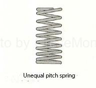
Figure 39-1: Valve spring
For the unequal pitch spring shown in Fig. 39-1, assemble the spring with the larger mass and the narrower pitch toward the cylinder head.
Valve seat
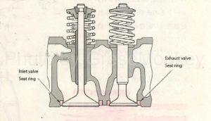
Figure 40: Valve seat ring
The valve seat is the part that is in close contact with the valve face and keeps the combustion chamber confidential.
Similarly, heat resistance and wear resistance are required.
The valve seat is generally press-fitted or cold-fitted with a special steel valve seat ring as shown in FIG. 40.
The angle of the contact surface between the valve face and the valve seat ring is generally 45 °.
Valve opening / closing mechanism
The valve opening / closing mechanism transmits the rotation of the crankshaft to the camshaft and operates the rocker arm or tappet to open / close the valve.
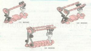
The OHC type valve opening / closing mechanism has one camshaft (SOHC) as shown in Fig. 34-8 (1) and two camshafts as shown in Fig. 34-8 (2) (3) ( DOHC). In the case of using two camshafts, in the case of Fig. (2), timing belts are hung on both camshaft gears and driven by the crankshaft, and in Fig. (3), one camshaft is the timing belt. It is driven, and the other is driven by a drive gear and a driven gear. Compared to the one in Fig. (2), one camshaft on one side receives direct drive from the crankshaft, so the distance between the two camshafts is increased. It can be set narrowly, and has the advantage that the cylinder head can be compactly assembled. (EX: Toyota high-mechanical twin cam system, etc.)
Currently, passenger cars that employ timing chains designed to reduce driving noise and improve durability are the mainstream.
Timing belt chain
Timing belts and timing chains are for transmitting the rotation of crankshaft timing gears to camshaft timing gears. Cog belts with gear teeth are used for timing belts, but timing chains are generally used. A special structure called a silent chain with less chain noise is used.
Figure 37: Valve mechanism
Tensioner
The tensioner is used to stretch the belt or chain to prevent the valve timing and ignition timing from getting out of order or making noise when the belt or chain bends or stretches due to fluctuations in engine rotation. Is always kept in an appropriate state, and an automatic adjustment type is used.
The automatic adjustment type uses hydraulic pressure and a spring to automatically adjust the timing belt so that it always maintains an appropriate tension.
Timing gear
The timing gear (also called timing sprocket) correctly conveys the opening / closing timing and ignition timing of the valve. It consists of a crankshaft timing gear (crankshaft sprocket) and a camshaft timing gear (camshaft sprocket), and is a camshaft. The timing gear is designed to make one rotation when the crankshaft timing gear is rotated twice.
Camshaft
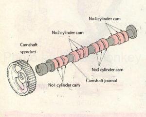
Figure 44: Camshaft
The camshaft is generally a forged product of cast iron or carbon steel, and the cam surface is high-frequency hardened.As shown in Fig. 44, the camshaft is generally equipped with a set of inlet cam and exhaust cam per cylinder, and is an OHC type. In the engine of, the journal part is supported by the cylinder head.
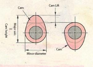
Figure 45: Cam shape
The shape of the cam is an egg shape as shown in Fig. 45. The major axis of the cam is called the height of the cam, and the difference between the major axis and the minor axis of the cam is called the cam lift.
The camshaft is provided with an oil hole for lubrication, and oil is supplied from the oil pump through the oil hole.
Rocker arm
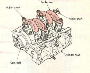
Figure 46: Rocker arm installation
The rocker arm transmits the movement of the cam to the valve stem to open and close the valve. It is attached to the rocker shaft as shown in Fig. 46, and is a seesaw type or a swing arm type that does not use a rocker shaft. There is a thing.
An adjust screw is generally incorporated in the rocker arm, and this screw adjusts the gap between the valve stem and the rocker arm, that is, the valve clearance.
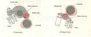
Figure 47: Roller rocker arm
Further, in order to reduce wear due to friction of the portion that transmits the movement of the cam to the rocker arm, a roller rocker arm in which a needle roller is provided on the rocker shaft is used as shown in FIG. 47.
Tappet
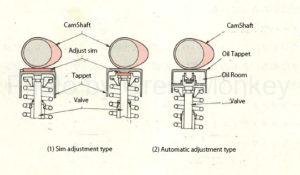
Figure 48: Valve clearance adjustment method
The tappet is used for the OHV type valve opening / closing mechanism, and is used for the direct motion type in which the cam of the camshaft directly pushes down the valve without the rocker arm among the OHC type.
To adjust the valve clearance of the OHC type tappet, use the shim adjustment type as shown in Fig. 48 (1) and the automatic adjustment that keeps the valve clearance at zero using hydraulic pressure as shown in Fig. 48 (2). There is a formula.