formula 2006 type Daihatsu Mira model: DBA-L275S engine model: KF-VE mission model: C0B-B1 type CVT mileage: 2,646km
The function of the automobile sensor is to send some signal to the actuator which detects the input and performs the operation. Therefore, the trouble of the sensor has only two ways, whether the input is detected correctly or the signal is not sent correctly.
We introduce the actual measurement result of what kind of signal the sensor used in the car of Daihatsu Mira (engine model: KF-VE) is operating the actuator and the waveform observed by the oscilloscope .
FIG. 1 shows a device arrangement diagram of the KV-VE type engine, FIG. 2 shows a terminal diagram of the engine DLC connector, and FIG. 3 shows a terminal arrangement diagram of the engine control unit (ECU).
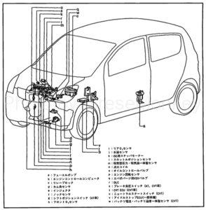
Figure 1: Device layout of KF-VE engine
Engine adjustment
Inspection of ignition timing and idling speed
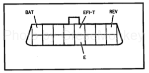
Figure 2: DLC connector of KF-VE engine
Clamp the timing light to the connector for connection. Similarly, the engine tachometer clamps to the wire harness of the first ignition coil. Then short-circuit the EFI-T to E terminals of the DLC connector shown in Fig. The ignition timing reference value at that time is 10 ± 2 ° BTDC / 850 to 100 rpm. (N or D position, not adjustable.)
Check the engine idling speed after warming up. The reference value is 900 + 100, -50 rpm.
Self-diagnosis (Diagnosis)
It is possible to read with the conventional engine check lamp. When the IG switch is ON, short-circuiting the EFI-T to E terminals of the DLC causes the engine check lamp in the combination meter to flash and repeatedly displays the abnormal code in ascending order of the number.
To erase the diagnosis code, it is OK to lock the IG switch, remove the EFI fuse (15 A) and connect the fuse for 60 seconds elapse.
Sensor signal output waveform
Below, we introduce the waveform of the real sensor’s oscilloscope. The numbers in parentheses are terminal numbers of the engine control unit (ECU).
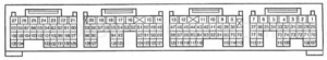
Figure 3: ECU terminal diagram of the KF-VE engine
Engine rotation sensor · Cam angle sensor
The engine rotation sensor N + signal (59), the N – signal (128) / the cam angle sensor N 2 + signal (58), and the N – signal (127) are both magnet type.
[Measured value]
- Engine rotation sensor N + signal
- Idling time: 1.25 V
- At 2500 rpm: 2.02 V
- Cam angle sensor N 2 + signal
- When idling: 0.85 V
- At 2500 rpm: 2.10 V
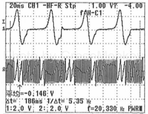
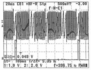
Output waveform of cam angle sensor signal (upper) and engine rotation sensor (lower) during idling
Output waveform of cam angle sensor signal (upper) and engine rotation sensor (lower) at 2500 rpm
Intake pipe pressure sensor PIM signal
Intake pipe pressure sensor PIM signal (52)
[Measured value]
- The intake air amount PIM
- Idling time: 1.90 V
- At 2000 rpm: 1.61 V
- At 4000 rpm: 1.50 V
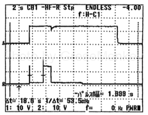
Throttle position sensor VTH signal
Throttle position sensor VTH signal (53)
[Measured value]
- Throttle position sensor VTH signal
- Fully closed: 0.58 V
- Full open: 3.95 V
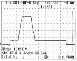
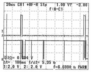
Output waveform of throttle sensor from IG OFF to ON → throttle fully closed → throttle full open → IG OFF
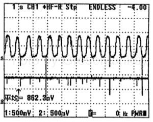
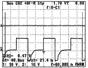
Front O 2 sensor · Rear O 2 sensor
Output waveform of front O2 sensor OX1 signal (123) / rear O2 sensor OX2 signal (18) idling and 2000 rpm
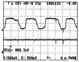
Front O2 sensor OX1 signal (upper) and rear O2 sensor signal (lower) during idling
Front O2 sensor OX1 signal (upper) and rear O2 sensor signal (lower) at 2000 rpm
Actuator (control system)
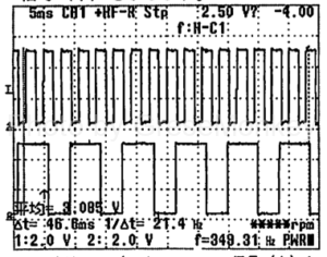
Fuel injection (fuel injector) control
Fuel injection (fuel injector) control # 10 (24), # 20 (23), # 30 (22): All cylinders simultaneous injection (cranking and acceleration), sequential injection (after starting) . The drive system of the injector is a voltage control type.
[Measured value]
- Cranking time injection time: 5.00 msec
- In idling time: 2.97 msec Operating voltage: 14.1 V
- 3000 rpm Hours of injection: 1.99 msec Operating voltage: 13.9 V
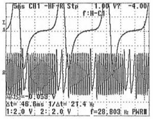
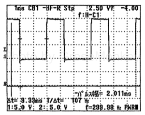
The waveform of the output signal (upper) of the injector # 10 at the time of idling and the waveform of the output signal (lower) of the injector # 30
Waveforms of the output signal (upper) of the injector # 10 and the output signal (lower) of the injector # 30 at 5000 rpm
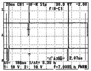
Ignition timing (igniter) control
Ignition timing (igniter) control IG1 (63), IG2 (62), TG3 (61): The distribution method is direct type (IG coil with power train).
Ignition coil # 1IG1 signal at the time of idling (upper) and Ignition coil # 3 output IG3 signal (lower) waveform
The waveform of the rotation sensor N + signal (upper) during idling and the ignition coil # 1 output IG 1 signal (lower)
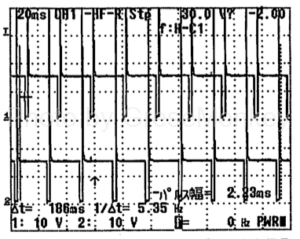
Ion current combustion control system
Ion current combustion control system ICMB 1 (51), ICMB 2 (50), ICMB 3 (49)
Ignition coil # 1 at idling Ignition signal (upper) and ion output # 1 Output waveform of ICBM 1 signal (lower)
Idle speed control
Idle speed control IACALo signal (66), IACABHi signal (67), IACBLo signal (68), IACBHi signal (69): Stepper motor type.
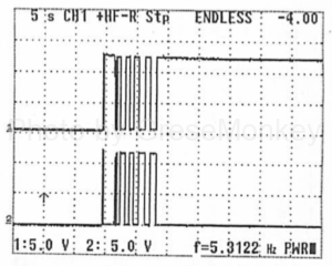
Stepper motor when changing IG ON → cranking → idling Output waveform of IACALo signal (upper) and IACAHi signal (lower)
Variable valve timing system
Variable valve timing system QCV + signal (26) · QCV – signal (25)
Output waveform of oil control valve OCV + signal (upper) and OCV – signal (lower) during idling
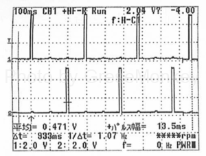
Fuel pump control
Fuel pump control FC2 signal (28)
It shows the output waveforms of IG SW signal (upper) and FC 2 signal (lower) when IG ON → cranking → idling → IG OFF is changed
CVT control Primary rotation sensor
CVT control primary rotation sensor NIN signal (B 35) · secondary rotation sensor NOI signal (B 34)
Output waveform of CVTNIN signal (upper) and NOI signal (lower) at a vehicle speed of 5 km / h
Similarly to the speed change control solenoid valve 1 with a vehicle speed of 5 km / h, it shows the output waveform of 2 (lower).