Inspection and maintenance of electronically controlled engine
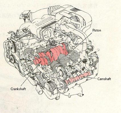
Figure 3: Horizontally opposed engine
In order to maintain the engine in good condition and fully demonstrate its performance, inspection and adjustment work such as inspection and maintenance is required. In addition, various functional parts that maintain these performances and require accurate operation also deteriorate in mechanical and electrical functions due to aging, which may cause phenomena such as engine malfunction. is there. In particular, as for the functional parts used in modern automobiles, many those related to electronic control systems, computer systems, etc. have been added to the conventional mechanical ones. Some of the applications are shared for engine-related and chassis-related, such as vehicle speed sensors, and some are composed of hybrid-related systems, and their usage methods are also diversifying.
However, despite technological innovation, the engine is always required to have some basics, such as quiet idling, sharp acceleration, high power, and low fuel consumption, as well as clean and reduced emissions. It is a requirement.
To achieve these, “strong compression pressure,” “appropriate ignition timing and strong sparks,” and “appropriate air-fuel mixture,” which are said to be the three elements of a gasoline engine, are indispensable.
Therefore, the engine inspection and maintenance here is based on the basic inspection method based on the three elements of these engines and the inspection method of the electronic control device, on the premise that the phenomenon of failure actually occurs. Starting with the diagnostic system, we will explain how to check the waveform using an oscilloscope, check the voltage and resistance of each sensor, and check the operation of the actuator.
table of contents
- Basic inspection
- Simple fuel pressure inspection
- Inspection of fuel pump system
- Inspection of injector system
- Inspection of self-diagnosis system
- Inspection of rotation signal system
- Inspection of throttle position sensor system
- Inspection of water temperature sensor system
- Inspection of igniter system
- Inspection of ignition confirmation signal system
- Inspection of ignition instruction signal system
- Inspection of idle speed control system
Basic inspection
The following five inspection items will be carried out as <basic inspections> regarding the three elements of the gasoline engine, and related inspections will be carried out as necessary. The specific flowchart is divided into three cases of “engine start failure”, “output shortage / acceleration failure”, and “idling instability”, and is shown below. Please refer to each case for download. Since the flowchart is just a general example, you can create your own troubleshooting pattern by reading it as appropriate or adding inspection items according to the vehicle type and the situation of breakdown / malfunction. It may be interesting.
- Basic inspection items
- Battery voltage check
- Simple fuel pressure inspection
- Injector operation check
- Spark inspection
- Checking idle speed and ignition timing
- Flowchart (download link)
Simple fuel pressure inspection
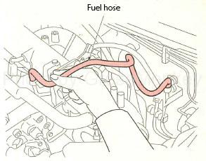
Figure 2: Simple fuel pressure inspection
When the fuel pump is operating, when the hose between the fuel filter and the delivery pipe is pinched as shown in Fig. 2, check that the hose is taut or pulsating.
If no tension or pulsation is felt, use a fuel pressure gauge to inspect.
Fuel pressure check
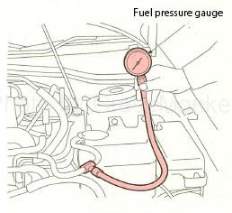
Figure 3: Installation of fuel pressure gauge
- Start the engine, remove the fuel pump relay, and stop the operation of the fuel pump.
- After the engine has stopped, crank it a couple of times to consume the fuel in the pipes.
- As shown in Fig. 3, after connecting the fuel pressure gauge between the fuel filter and the delivery pipe, install the fuel pump relay.
- Start the engine again and check that the fuel pressure when the vacuum hose of the pressure regulator is connected and when it is disconnected is within the specified values. (Usually, the fuel pressure when removed shows a slightly higher value.)
- If the fuel pressure is not within the specified value, check the pressure regulator, pipe clogging, hose twist, etc., and check the fuel pump system as shown below. (=> Inspection of fuel pump system)
Inspection of fuel pump system
Power check
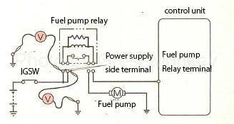
Figure 4: Power check
Turn off the ignition switch and remove the fuel pump relay. Next, turn on the ignition switch, measure the voltage between the power supply side terminal of the fuel pump relay and the ground as shown in Fig. 4, and confirm that it is within the specified value.
Inspection of control circuit
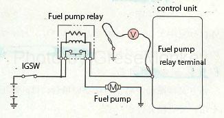
Figure 5: Inspection of control circuit
When the fuel pump relay is connected and the ignition switch is turned on, measure the voltage between the fuel pump relay terminal and the body ground as shown in Fig. 5 and confirm that it is within the specified value.

Figure 6: Wiring continuity check (1)
If it does not meet the specified value, turn off the ignition switch, remove the fuel pump relay, and check the continuity between the fuel pump relay terminal and fuel pump relay terminal of the control unit as shown in Fig. 6. If there is a problem. To fix.
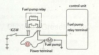
Figure 7: Wiring continuity check (2)
Also, when the fuel pump connector and fuel pump relay are removed, check the continuity between the fuel pump power supply terminal and the fuel pump relay terminal as shown in Fig. 7.
Inspection of ground circuit
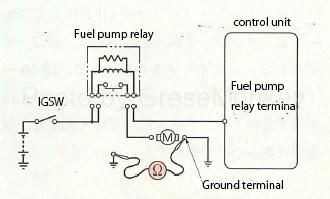
Figure 8: Inspection of ground circuit
As shown in Fig. 8, check the continuity between the ground terminal of the fuel pump and the body ground, and correct any problems.
Single inspection
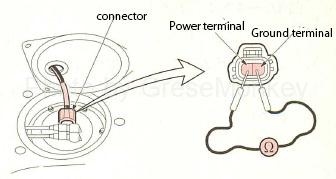
Figure 9: Checking the fuel pump
Remove the fuel pump connector, measure the resistance between both terminals of the connector as shown in Fig. 9, and confirm that it is within the specified value. Also, connect the power supply terminal directly to the positive side of the battery and the ground terminal to the negative side (direct connection), and check that the fuel pump operates.
If there is a problem with each, replace the fuel pump assembly.
Inspection of injector system
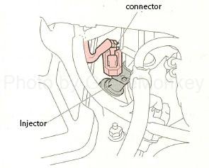
Figure 10: Injector operation check
Start the engine and check the operating noise with a sound scope, etc., or check that the engine speed drops momentarily when the injector connector is disconnected for each cylinder as shown in Fig. 10.
If the engine speed does not decrease and there is no operating noise, check the injector system (main unit system) shown below.
Power check
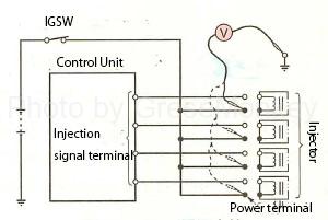
Figure 11: Power check
Remove the injector connector, turn on the ignition switch, and measure the voltage between the power terminal of the connector between the harnesses of each injector and the ground as shown in Fig. 11 and confirm that it is within the specified value.
Inspection of injection signal

Figure 12: Inspection of injection signal
With the engine started and the injector connector attached, connect an oscilloscope between the injection signal terminal of each injector and the ground as shown in Fig. 12, observe the injection signal waveform, and compare it with the normal signal waveform.
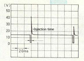
Figure 13: Injection signal waveform
FIG. 13 shows the normal injection signal waveform when idling. The period during which the voltage drops to near 0V is the injector ON time, that is, the injection time. In the example shown in the figure, it is about 2 ms (2/1000). Seconds).
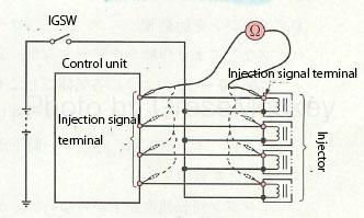
Figure 14: Inspection of control circuit
If the injection signal waveform is not normal, turn off the ignition switch, check the continuity of the harness of the injection signal circuit between the control unit and each injector as shown in Fig. 14, and correct any problems.
Single inspection
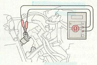
Figure 15: Injector inspection
Remove the injector connector, measure the resistance between the power supply terminal and signal terminal of each injector as shown in Fig. 15, and confirm that it is within the specified value. If it is not within the specified value, replace the injector as an assembly.
Inspection of self-diagnosis system
The self-diagnosis system will be inspected after the basic inspection has been carried out.
In relation to the electronic control system, due to the fail-safe function, even if a failure actually occurs, it may not appear as a failure phenomenon, so it is necessary to reliably implement it using the self-diagnosis code table according to the vehicle type.
Table 1 is an example of a self-diagnosis code table.
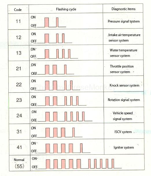
Table 1: Example of self-diagnosis code table
If the self-diagnosis system shows an abnormal code, it can be estimated that the displayed system is broken or short-circuited. Below, the related inspections will be explained using the code table in Table 1 as an example.
Inspection of rotation signal system
When the self-diagnosis system displays “rotation signal system” which is an example of abnormal system, it is displayed when the crank angle signal or crank angle reference position signal is not input for a certain period of time, and when each signal has missing teeth. Therefore, it is necessary to inspect these systems.
Checking the input signal
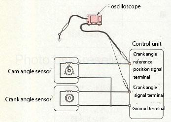
Figure 16: Checking the input signal
Start the engine, connect the oscilloscope between the crank angle reference position signal terminal or crank angle signal terminal of the control unit and the ground as shown in Fig. 16, observe the input signal waveform, and compare it with the normal signal waveform.
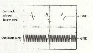
Figure 17: Crank angle sensor and cam angle sensor signal waveforms
FIG. 17 shows the normal signal waveforms of the crank angle sensor and the cam angle sensor when idling.
Circuit inspection
- Inspection of ground circuit
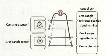
Figure 18: Inspection of ground circuit
Remove the connectors of the control unit, crank angle sensor, and cam angle sensor, and check the continuity between the sensor and the ground circuit of the control unit as shown in Fig. 18.
- Inspection of input circuit
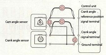
Figure 19: Inspection of input circuit
Remove the connectors of the control unit, crank angle sensor, and cam angle sensor, and check the continuity of the harness between the crank angle signal terminal and the crank angle sensor and between the crank angle reference position signal terminal and the cam angle sensor as shown in FIG.
Also, check the insulation status with the ground circuit as shown in the figure.
Single inspection
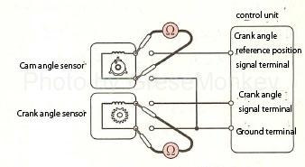
Figure 20: Single unit inspection
Remove the connectors of the crank angle sensor and cam angle sensor, and measure the resistance between the signal terminal and the ground terminal of each sensor as shown in Fig. 20 to confirm that they are within the specified values.
Inspection of throttle position sensor system
When the self-diagnosis system is an abnormal system “throttle position sensor system”, it is displayed when the circuit disconnection or short circuit of the throttle position sensor system continues for a certain period of time, so it is necessary to inspect these systems.
Power check

Figure 21: Power check
Remove the connector of the throttle position sensor, turn on the ignition switch, measure the voltage between the power supply terminal of the throttle position sensor and the body ground as shown in Fig. 21, and confirm that it is within the specified value.
Circuit inspection
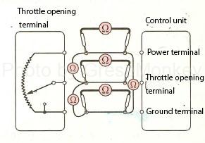
Figure 22: Circuit inspection
Remove the connectors of the control unit and throttle position sensor, and check the harness continuity status between the power supply terminal, throttle opening terminal, ground terminal and throttle position sensor as shown in Fig. 22.
Also, check the insulation between the harnesses as shown in the figure.
Single inspection
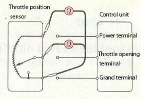
Figure 23: Single unit inspection
Remove the connector of the throttle position sensor, measure the resistance between the power supply terminal and the ground terminal as shown in Fig. 23, and confirm that it is within the specified value.
Also, measure the resistance when the throttle between the throttle opening terminal and the ground terminal is fully opened and fully closed, and confirm that it is within the specified value.
Inspection of water temperature sensor system
When the self-diagnosis system displays the abnormal system “water temperature sensor system”, it is displayed when the circuit of the water temperature sensor system is broken or short-circuited, so it is necessary to inspect these systems.
Voltage check
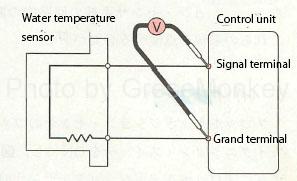
Figure 24: Voltage check
Turn on the ignition switch and measure the voltage between the signal terminal and the ground terminal of the water temperature sensor as shown in Fig. 24, and confirm that it is within the specified value.
Circuit inspection
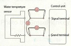
Figure 25: Circuit inspection
Remove the connectors of the control unit and water temperature sensor, and check the harness status between the signal terminal and ground terminal and the water temperature sensor as shown in Fig. 25. Also, check the insulation status with the ground circuit as shown in the figure.
Single inspection
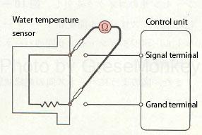
Figure 26: Single unit inspection
Remove the connector of the water temperature sensor, measure the resistance between the signal terminal and the ground terminal of the water temperature sensor as shown in Fig. 26, and confirm that it is within the specified value.
Inspection of igniter system
When the self-diagnosis system displays the abnormal system “igniter system”, when the ignition confirmation signal is not input for a certain period of time even though the ignition instruction signal of the igniter system is output, and between the control unit and the ignition coil. It is necessary to inspect these systems because they are displayed when there is a disconnection or short circuit in the ignition instruction signal and ignition confirmation signal.
The igniter, which is a component of the igniter system, has many built-in IC parts, and it is difficult to inspect the igniter alone. Judge and replace the parts.
Here, the first cylinder of the direct ignition system will be described as an example.
Spark inspection
Perform a spark check to see if there is something wrong with either the ignition indicator signal system or the ignition confirmation signal system. Perform a spark inspection, and if sparks fly to the spark plug, there is an abnormality in the ignition confirmation signal system, and if no sparks fly, there is an abnormality in the ignition instruction signal system, so inspect each system.
Inspection of ignition confirmation signal system
Circuit inspection
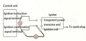
Figure 27: Circuit inspection
Remove the connectors of the control unit and igniter, and check the continuity and insulation status of the harness between the ignition confirmation signal terminal and the igniter as shown in Fig. 27.
Voltage check
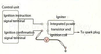
Figure 28: Voltage check
Remove the igniter connector, turn on the ignition switch, measure the voltage between the ignition confirmation signal terminal and ground as shown in Fig. 28, and confirm that it is within the specified value.
Check the circuit and voltage, and if there are no abnormalities, replace the igniter and check that the system is normal.
Inspection of ignition instruction signal system
Circuit inspection
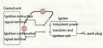
Figure 29: Circuit inspection
Remove the connectors of the control unit and igniter, and check the continuity and insulation of the harness between the ignition instruction signal terminal and the igniter as shown in Fig. 29.
Voltage check

Figure 30: Voltage check
Remove the igniter connector, and at the time of cranking, measure the voltage between the ignition instruction signal terminal of the control unit and ground as shown in Fig. 30 and confirm that it is within the specified value.

Figure 31: Oscilloscope waveform
Also, observe the ignition instruction signal waveform with an oscilloscope and compare it with the normal signal waveform. FIG. 31 shows the ignition signal waveform and the ignition confirmation signal waveform at the time of idling.
Inspection of idle speed control system
If the self-diagnosis system displays the abnormal system “idle speed control valve system (ISCV)”, it will be displayed when the circuit of the idle speed control system is broken or short-circuited, so check these systems. There is a need.
ISCV (rotary valve type), which is a component of the idle rotation speed control system, is difficult to judge whether it is good or bad by individual inspection of resistance, etc., so after checking the control unit, harness, etc. and confirming that there are no abnormalities, ISCV abnormality Judging that, replace the parts.
Power check
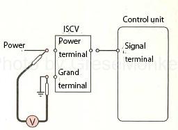
Figure 32: Power check
When the ISCV connector is removed and the ignition switch is turned on, measure the voltage between the ISCV power supply terminal and the ground terminal as shown in Fig. 32, and confirm that the voltage is within the specified value.
Circuit inspection
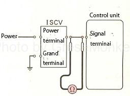
Figure 33: Circuit inspection
Remove the control unit and ISCV connector, and check the continuity of the harness between the signal terminal and ISCV as shown in Fig. 33.
Signal waveform inspection

Figure 34: Signal waveform inspection
Observe the output signal waveform with an oscilloscope as shown in Fig. 34 and compare it with the normal signal waveform.
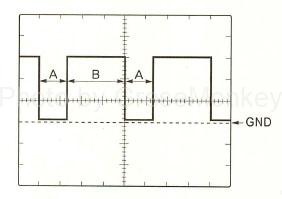
Figure 35: ISCV signal waveform
Figure 35 shows the normal signal waveform of ISCV when idling. ISCV turns on at A in the figure and turns off at B.
Therefore, when the idle rotation speed decreases due to a load or the like, the part A (ON time) is lengthened to increase the rotation speed.