Disassembly and maintenance of reciprocating engine
Explains the main points of inspection / correction and disassembly / assembly of the main parts that make up the main body of the reciprocating engine.
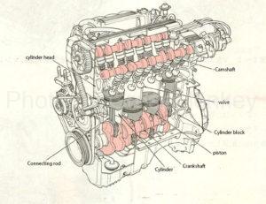
table of contents
- Cylinder head inspection and correction
- Cylinder head disassembly and maintenance
- Inspection and correction of cylinders and cylinder blocks
- Inspection and correction of pistons, piston pins and piston rings
- Key points of piston disassembly
- Key points of piston assembly
- Inspection and correction of connecting rods and connecting rod bearings
- Key points for disassembling the connecting rod and connecting rod bearing
- Key points for assembling connecting rods and connecting rod bearings
- Inspection and correction of crankshaft and journal bearings
- Key points for disassembling the crankshaft and journal bearings
- Key points for assembling crankshafts and journal bearings
- Check and correct flywheel and ring gear
- Key points for disassembling and assembling the flywheel and ring gear
- Inspection and correction of valve mechanism
- Key points of disassembling and assembling the valve mechanism
Cylinder head inspection and correction
Inspection of carbon, scale, rust, etc.
Check the adhesion of carbon around the exhaust port and valve seat, and be careful not to damage the valve seat, especially when removing the carbon on the underside of the cylinder head.
Inspect the water jacket for scale and rust, and clean any significant ones.
In addition, significant oil adhesion to the inlet port is often caused by oil dropping from the inlet valve, and dust adhesion is often caused by a defective air cleaner, so the situation before disassembly can be judged from these. it can.
Inspection of cracks and strain
After removing the carbon adhering to the underside of the head, inspect the cracks in each part such as around the valve seat.
If necessary, cracks are inspected by the dye penetrant inspection method, which is one of the non-destructive inspection methods. Replace those with cracks.
Check the strain on the lower surface of the head and the manifold mounting surface as shown in Fig. 1, and apply the straight edge in 6 directions A to F on the lower surface of the head and 3 directions G to I on the manifold mounting surface. Insert a thickness gauge to measure.
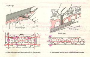
Figure 1: Cylinder head strain measurement
The straight edge used at this time must be of a length that can be applied to the front surface of the head.
For sensitive strain, polish it with a surface grinder or oil stone to correct it, but if the strain is significant, replace it.
Cylinder head disassembly and maintenance
Cylinder head removal
Be sure to loosen and remove the tightening bolts of the cylinder head from the outside to the center alternately in two steps according to the specified order. In particular, if it is performed when the temperature of the cylinder head is high, the cylinder head may be distorted, so be careful.
Since some tightening bolts have different lengths, they are classified so that they can be understood at the time of assembly.
Installation of cylinder head
Assemble the cylinder head gasket by paying attention to the vertical orientation and aligning it with the positioning pin on the upper side of the cylinder block. Also, be careful not to forget that liquid packing may be applied or O-rings or rubber packing may be inserted into the passage holes for lubricating oil and cooling water from the cylinder block to the head.
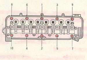
Figure 2: Tightening sequence
When installing the cylinder head bolt, blow off the water or oil that has accumulated in the bolt hole of the cylinder block with an air gun, etc., and then apply a thin layer of engine oil to the threaded part of the cylinder head bolt. Tighten from the bolt to the outer bolt.
Note that tightening the bolts with water or oil in the bolt holes may damage the cylinder block.
When tightening, use a torque wrench and divide it into 2 to 3 times with the specified torque. If the tightening method is specified in the maintenance manual, such as the plastic tightening method, follow the specified tightening procedure.
Plastic zone tightening method
Bolts are usually tightened in an elastic range (a position where the tightening condition can be confirmed) in which the tightening torque and the rotation angle of the bolt increase in proportion. The plastic tightening method further tightens the bolt in this elastic region, and by performing it in the plastic region where only the rotation angle of the bolt changes and the tightening torque and axial force do not change, the axial force varies due to the variation in the rotation angle. A stable axial force can be obtained, and at the same time, a large axial force itself can be obtained, improving reliability.
Inspection and correction of cylinders and cylinder blocks
Cylinder inspection
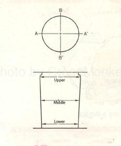
Figure 3: Cylinder wear direction and measurement points
For the cylinder, inspect the inner diameter for wear, damage, and cracks.
Since the wear tendency of the cylinder is generally as shown in Fig. 3, the inner diameter is measured at three points, upper, middle, and lower, in the axial direction (A-A’) of each crankshaft and in the direction perpendicular to it (B). -B’) is performed at a total of 6 locations using a cylinder gauge as shown in Fig. 4.
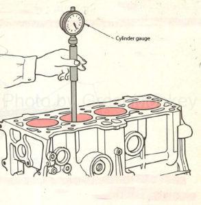
Figure 4: Measurement of cylinder inner diameter
As a result of measuring the inner diameter of the cylinder, if the wear is significant, boring (cutting to oversize) and honing (polishing the inner surface of the cylinder after boring) are performed to correct the inner diameter to fit the oversized piston.
Also, depending on the engine, the cylinder liner may be replaced.
Inspection of cylinder block
The cylinder block is inspected for distortion and cracks on the upper surface, water stains and rust in the water jacket, and clogging of the cooling water passage and oil passage.
Check the top surface of the block and the strain in the same way as when measuring the strain on the bottom surface of the cylinder head, measure with a straight edge and thickness gauge, and if the measured value is above the specified value, polish it with a surface grinder or oil stone. Fix it.
The cracks are inspected by inspecting the screw holes of the cylinder head bolt and, if necessary, by the dyeing penetration point commercial method or the like.
Clean the waterways and oil channels with an air gun. In this case, note that water stains and rust may have accumulated on the lower part of the water jacket.
Inspection and correction of pistons, piston pins and piston rings
Piston inspection
For the piston, remove the carbon stuck to the head and ring groove, and inspect the degree of cracks, scratches, wear, etc.
For cracks, also examine the hard-to-see part behind the piston ring groove. The piston head may be burnt out due to abnormal combustion, so check it carefully.
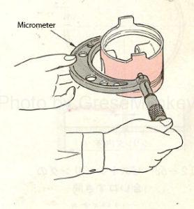
Figure 5: Measurement of piston outer diameter
The outer diameter of the piston is measured using a micrometer as shown in FIG. 5 at the skirt portion in the direction perpendicular to the piston boss direction.
To measure the wear of the piston ring groove, insert a new ring into the ring groove and use a thickness gauge as shown in Fig. 6 to make gaps between the ring and the ring groove door at several points on the outer circumference.
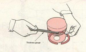
Figure 6: Measurement of clearance between ring and ring groove
If the gap is large, it may cause compression leakage or oil rise, so replace the piston and ring as a set.
Check the oil return hole after removing the carbon from the oil ring groove. If the hole is clogged, the scraped oil will not escape into the piston and cause the oil to rise, so use a wire or the like. to clean.
Inspection of piston ring
For piston rings, check the gap at the abutment.
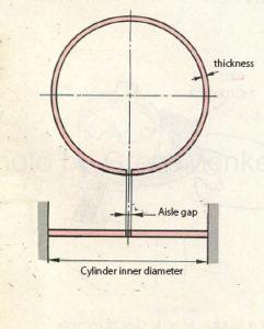
Figure 7: Piston ring joint gap
The abutment gap is a gap formed at the joint of the ring when it is installed in the cylinder as shown in Fig. 7, and is provided to prevent the ring from expanding and hitting at high temperature during operation. ..
The gap between the joints increases as the ring wears and becomes thinner.
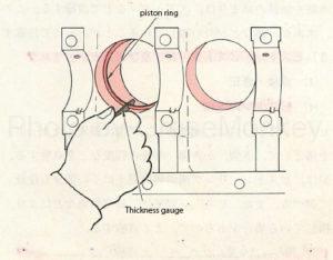
Figure 8: Measurement of the gap in the piston ring
To check the gap, push the piston head correctly into the lower part of the cylinder with less ring wear so that it is perpendicular to the cylinder, measure with a thickness gauge as shown in Fig. 8, and replace the one whose measured value exceeds the specified value. To do. Also check the tension of the ring.
Key points of piston disassembly
When disassembling the piston, the main points of pulling out the piston from the cylinder, removing the ring from the piston, and pulling out the piston pin will be explained.
- When the piston is pulled out from the cylinder, the crankshaft is rotated, the piston is set to the top dead center position, the connecting rod cap is removed, and then the piston is pulled out to the cylinder head side and arranged in the cylinder order. In this case, if the carbon adhering to the upper part of the cylinder wall surface is removed in advance with a scraper or the like, the work can be easily performed without the ring getting caught. Also, to prevent it from being pulled out by hand when pulling it out, put a piece of wood on the connecting rod and tap it lightly.
- To remove the ring from the piston, use a piston ring replayer as shown in Figure 9.
- For the piston pin, remove the snap ring with pliers, press an appropriate pad against the piston, and pull it out with a press. In addition to this, there is also a method of heating the piston with a piston heater as shown in FIG. 10, expanding it, and then removing the piston.
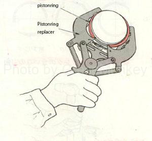
Figure 9: Piston ring removal
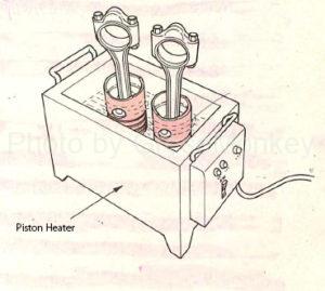
Figure 10: Piston heater
Key points of piston assembly
- There are two types of pistons, one is to assemble the piston pin at room temperature by tapping or using a press, and the other is to preheat the piston pin with a piston heater or the like and insert the piston pin. After assembling the piston pin, securely install the snap ring in the groove.
- When assembling the piston and connecting rod, be careful not to misorient them in the front-rear direction. Generally, the front direction of the piston and the connecting rod is identified by adding a symbol in advance. After combining the pistons, try moving the connecting rod back and forth by hand, as long as you feel some resistance.
- When assembling the piston ring, be careful not to make a mistake in the ring assembly position and vertical orientation. Generally, there is an inscription on the upper side of the ring to indicate this. When assembling, use a piston ring replayer and be careful not to damage the piston with the ring.
- When assembling the piston to the cylinder, it is important that the minimum clearance between the piston and the cylinder is appropriate. If the gap is too small, it causes seizure of the piston, and if it is too large, it causes a decrease in output or a tapping sound due to compression leakage. The minimum gap can be known by measuring the minimum inner diameter of the cylinder and the maximum outer diameter of the piston, respectively.
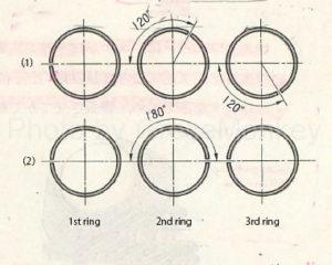
Figure 11: Direction of the piston ring joint gap
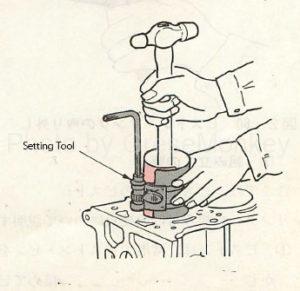
Figure 12: Piston insertion
- If the gap between the piston and the cylinder is appropriate, insert the piston assembled to the connecting rod into the cylinder. At this time, as shown in FIG. 11, the direction of the abutment gap of the rings is shifted so as not to match the abutment direction of the adjacent rings. This is because if the directions match, the combustion gas tends to leak from this portion. In addition, care should be taken that the direction of this abutment is not in the lateral pressure direction of the piston (crank side direction), that is, in the direction in which the piston pushes the cylinder wall (boss direction) during combustion and in the crankshaft axial direction.
- Correct the direction of the connecting rod, apply engine oil to the outer circumference of the piston, be careful not to make a mistake in the assembly direction of the piston, and tap the piston head with a piece of wood using the setting tool as shown in Fig. 12. , Push in until the connecting rod bearing hits the crank pin.
- Further, while pushing the piston, rotate the crankshaft, assemble the connecting rod cap at the bottom dead center position, and tighten the bolt to the specified torque. At this time, be careful not to make a mistake in the orientation of the connecting rod cap. Also, after tightening, check that the crankshaft rotates smoothly.
Inspection and correction of connecting rods and connecting rod bearings
Check for wear on the side of the large end of the connecting rod
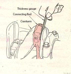
Figure 13: Checking for wear on the side of the large end of the connecting rod
Tighten the connecting rod to the crank pin with the specified torque, measure the gap between the side surface of the large end and the end surface of the crank pin with a thickness gauge as shown in Fig. 13, and replace the connecting rod if the measured value is greater than or equal to the specified value.
If the wear is significant and the play is too large, the connecting rod will move back and forth, causing noise.
Checking the wear of the connecting rod small end bush
The small end bush is attached to the connecting rod and checked for wear. This portion rotates and slides between the piston pin and the bush, and is particularly struck in the vertical direction, so that it tends to wear in an elliptical shape.
Therefore, for the bush, the wear in the vertical direction of the connecting rod and in the direction perpendicular to it is measured with a pinhole gauge or the like, and if the gap is greater than or equal to the limit due to the difference from the outer diameter of the piston pin, the bush is replaced.
Check for wear, damage and tension on connecting rod bearings
For connecting rod bearings, check the inner surface for seizure and scratches, and for partial metal peeling from the back metal.
In addition, the tension of the bearing gradually decreases as the load is repeated, so it is necessary to thoroughly inspect it when reusing it after disassembly.
The gap between the crank pin and the bearing is called the oil clearance, which is necessary to keep the oil in this part, prevent the metals from coming into direct contact with each other, and rotate the crank pin smoothly. If this clearance becomes too large due to wear, oil will flow out, the oil pressure will drop, the amount of oil sent to other parts will decrease, and the lubrication function will not be possible.
On the contrary, if the oil clearance is too small, the bearing heats up and causes seizure.
Therefore, when replacing bearings, work with proper oil clearance in mind.
The oil clearance is measured by measuring the outer diameter of the crank pin with a micrometer, temporarily assembling a connecting rod bearing that matches this, and obtaining the oil clearance from the difference from the outer diameter of the crank pin.
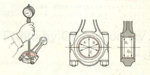
Figure 14: Measuring the inner diameter of the connecting rod bearing
The measurement positions of the connecting rod bearing inner diameter are D1 and D2 in the A, B, and C directions shown in FIG. 14, respectively.
Another method is to measure the oil clearance using a plastigauge.
The plastigauge is a thin wire made of synthetic resin, and there are three types that are color-coded according to the measurement range of the clearance.
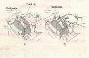
Figure 15: Measurement of oil clearance with plastigauge
To measure with a plus and gauge, first thoroughly clean the connecting rod cap bearing and crank pin, wipe off oil, etc., then cut the plastigauge to the bearing width and place it on the crank pin as shown in Fig. 15 (1). Place it parallel to the shaft, avoiding hot water holes, cover it with a connecting rod cap, and tighten it to the specified torque.
At this time, the crankshaft must never be rotated.
Next, remove the connecting rod cap and read the oil clearance value by aligning the widest part (minimum clearance part) of the crushed plastigauge with the scale table marked on the plastigauge package as shown in Fig. 15 (2). ..
Check for deformation of bearing housing and cap
To check the deformation of the bearing housing and cap, measure the location shown in FIG. 14 using a cylinder gauge in the same manner as when measuring the inner diameter of the bearing. As a result of the measurement, replace the one with a marked deviation in roundness or uneven wear.
Check for deformation and damage to connecting rod cap bolts and bolt holes
Connecting rod cap bolts are especially inspected for crushed and stretched threads, as well as cracks and damage.
Also, inspect the cap and connecting rod bolts in the same way, and check the state of wear by inserting new bolts.
If there is a problem with the bolt or bolt hole, not only will the bolt be loosened and the bolt will break, but the mating surface of the bearing will shift, causing damage to the crank pin.
Key points for disassembling the connecting rod and connecting rod bearing
Since the connecting rod is pulled out together with the piston, the precautions in that case and the pulling out of the small end bush will be explained here.
- Cylinder numbers and the like are generally stamped on the side surface of the large end, so check the direction of the stamped surface so that you do not make a mistake when assembling.
- To remove the small end bush, use a detachable tool as shown in Fig. 16 and apply a pad that matches the attachment to remove it with a press.
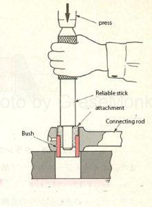
Figure 16: Extraction of connecting rod small end bush
Key points for assembling connecting rods and connecting rod bearings
Press-fitting the small end bush and assembling it to the crankshaft
- The small end bush is press-fitted by pressing using a detachable tool used at the time of disassembly. If there is a hole at the small end, press fit the oil hole in the bush accordingly.
- When the bush is replaced, the inner diameter of the bush is slightly deformed by press fitting, so finish it to the specified size through a reamer so that the gap in the piston focus is appropriate.
- When assembling the connecting rod to the crankshaft, be careful not to make a mistake in the orientation of the connecting rod and cap.
- To tighten the cap, first use a box wrench or the like to tighten it to some extent, and finally use a torque wrench to tighten it to the specified torque. If the tightening method such as the plastic region tightening method is specified as in the case of the cylinder head, the tightening method is followed.
Inspection and correction of crankshaft and journal bearings
Check for crankshaft wear
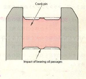
Figure 17: Crank pin wear tendency
Wear of the journal portion and pin portion of the crankshaft causes the oil clearance to increase along with the wear of the bearing, which causes a decrease in oil pressure and an abnormal engine noise.
The measurement of oil clearance is basically the same as the measurement method for connecting rods.
Since the measurement points are as shown in Fig. 17 as a general tendency of wear, as shown in Fig. 18, the arrows in the A-A’and B-B’ directions in the middle part avoiding the positions of the central part and both ends. It becomes a part (D1, D2, d1, d2).
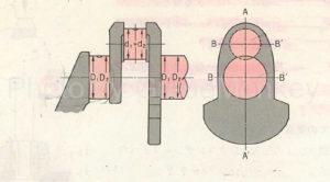
Figure 18: Crankshaft journal diameter and pin diameter measurements
If the oil clearance exceeds the specified value, replace the bearing or polish the crankshaft with a crankshaft grinder and use an undersized bearing to correct it.
Also, check for wear on the part of the oil seal that hits the lip.
Checking the bending of the crankshaft
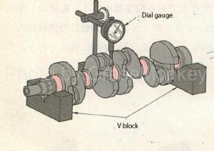
Figure 19: Crankshaft runout measurement
To check the bending of the crankshaft, place it on the V block on the surface plate as shown in Fig. 19, apply a dial gauge to the journal part in the center of the crankshaft, and gently rotate the crankshaft in one direction to measure the runout. To do.
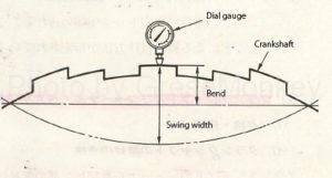
Figure 20: Crankshaft runout and bending
The bend is half of the runout as shown in Fig. 20, and the light bend can be corrected by polishing with a crankshaft grinder, but the one that exceeds the limit is replaced.
Check for cracks in the crankshaft
Visually inspect the entire crankshaft to check for scratches on the journal and pins, and for cracks, inspect the base of each arm and the vicinity of the oil hole using a dye penetrant inspection method, etc., and replace any cracks.
Checking the axial play of the crankshaft
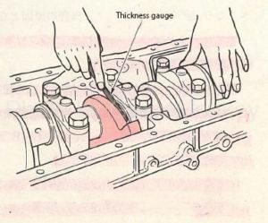
Figure 21: Measurement of crankshaft axial play
This inspection is performed using a thickness gauge before removing the crankshaft as shown in Fig. 21, to determine whether or not the thrust bearing needs to be replaced, and to confirm whether or not it has been assembled to the specified value after assembly.
Check for wear on journal bearings
Similar to connecting rod bearings, journal bearings should be inspected for the condition of the inner surface and for wear.
Inspection of bearing cap and housing for distortion and damage
Inspect the bearing cap and the inside of the housing for distortion and damage.
If the housing and cap are distorted, the adhesion between the bearing and the inner surface of the housing will be poor, and heat conduction and contact with the bearing will be poor, causing premature wear and damage to the bearing.
Further, if the center between the housings is deviated due to distortion, if the crankshaft is assembled as it is, the crankshaft cannot rotate smoothly, which may cause damage to the bearing.
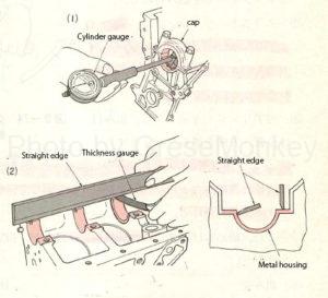
Figure 22: Measurement of housing center deviation
To check for distortion, tighten the cap to the housing to the specified torque, and then measure with a cylinder gauge as shown in Fig. 22 (1).
To check for center deviation, apply the straight edge to the contact surface and inner surface of the housing with the cap, and measure the gap between the housing and the straight edge with a thickness gauge, as shown in Fig. 22 (2).
Inspection and replacement of oil seals
Inspect the oil seal lip and the part that penetrates the retainer on the outer circumference of the oil seal, and if it is defective, replace it. When installing a new oil seal, apply a thin layer of the specified grease to the lip.
Key points for disassembling the crankshaft and journal bearings
Key points when removing the crankshaft from the cylinder block
- Before removing the crankshaft, measure the play in the crankshaft direction with a thickness gauge to determine whether or not the thrust bearing needs to be replaced.
- Loosen the tightening bolts of the journal bearing cap from both ends to the center, and remove the bearing cap. The bearing cap is generally engraved with a number indicating its position, but the front-back orientation is also important when assembling, so mark it and organize it.
- After removing the crankshaft, pull out the bearing on the housing side and write the position number on the back of the bearing so that the assembly position is correct.
Key points for assembling crankshafts and journal bearings
Key points when assembling the crankshaft to the cylinder block
- Before assembling, clean each part such as bearing, bearing housing, crankshaft to prevent foreign matter from adhering, apply engine oil to rotating parts, and assemble the crankshaft to the cylinder block.
- Be careful not to forget to insert the thrust bearing as it may be a single bearing that is not integrated with the journal bearing.
- Make sure that the bearing cap is in the correct assembly position and direction, and the tightening bolts rotate from the center to both ends in order, using a torque wrench as shown in Fig. 23, to rotate the crankshaft each time it is tightened. Check if it is smooth, and finally tighten it to the specified torque. If the tightening method is specified, such as the plastic region tightening method, follow the specified tightening procedure.
- After assembling, rotate the crankshaft by hand and check that it rotates smoothly.
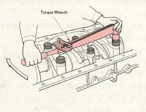
Figure 23: Tightening the journal bearing cap
Check and correct flywheel and ring gear
Checking the runout of the flywheel
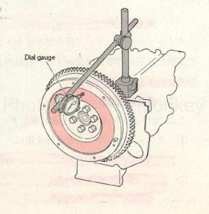
Figure 24: Flywheel runout measurement
The runout of the flywheel may cause a poor clutch connection, so measure it using a dial gauge as shown in Fig. 24, and replace it if the runout exceeds the specified value.
Check for cracks and stepped wear on the clutch disc contact surface
The contact surface may be cracked or stepped and worn due to repeated frictional heat with the clutch disc. If there is a problem such as wear, polish or replace it.
Check for cracks and damage in flywheel mounting bolt holes
Visually inspect the area around the flywheel mounting bolt holes and replace any cracks or damage.
Check for wear and loss of ring gear
Ring gears are inspected for cracks and missing teeth. If there is a return on the tooth surface, use a file to correct it.
To replace the ring gear, place a pad on the ring gear, hit each part around the gear with a hammer evenly, and when changing to a new one, heat the ring gear evenly so that the orientation is correct. It fits on the outer circumference of a flywheel at room temperature and cools naturally in the atmosphere.
Key points for disassembling and assembling the flywheel and ring gear
The flywheel is positioned with the crankshaft with a knock pin or the like, but if there is no knock pin, mark the crankshaft and flywheel together before disassembling.
Also, when assembling the flywheel to the crankshaft, clean it thoroughly so that foreign matter such as metal powder does not get mixed in between it, then attach it carefully to the alignment mark or knock pin, and divide each bolt diagonally several times alternately. After tightening, finally tighten to the specified torque.
After assembly, use a dial gauge to check for flywheel runout.
Inspection and correction of valve mechanism
Valve inspection
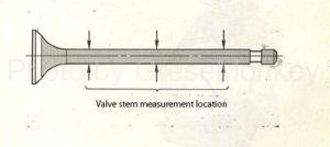
Figure 25: Measurement of valve stem outer diameter
As shown in Fig. 25, measure the outer diameter of the valve stem at three points with a micrometer, and replace the valve stem if it is worn, burnt, or deformed beyond the specified value.
Also, check the valve face and valve stem end for damage, wear, etc., and if there is a problem, fix it with a valve facer or replace it.
Checking the gap between the valve guide and valve stem guide
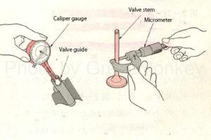
Figure 26: Gap measurement between valve guide and valve stem
In general, as shown in Fig. 26, the guide and stem are inspected by measuring the inner diameter of the valve guide with a caliper gauge and the outer diameter of the valve stem with a micrometer, and finding the gap from the difference between the inner diameter and outer diameter, which exceeds the specified value. If so, replace the valve and guide as a set.
In addition to this, there is a method in which a valve is incorporated in a valve guide, a dial gauge is applied to the valve, the tip of the valve is moved, and the movement (gap) at this time is measured.
The valve guide oil seal should be inspected for deformation, uneven wear, scratches, etc. on the inner surface of the lip. As a general rule, once removed, the oil seal will not be reused.
Inspection of valve spring
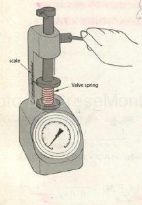
Figure 27: Spring force and free height measurement with a spring tester
Inspect the appearance of the valve spring, check for damage, and replace any defective one.
The spring force of the spring is measured by attaching the spring with a spring tester and compressing it to the height as shown in Fig. 27. If the value is not the specified value, replace the spring.
The free height of the spring is measured using the scale of the spring tester, and if it is less than the specified value, it is replaced.
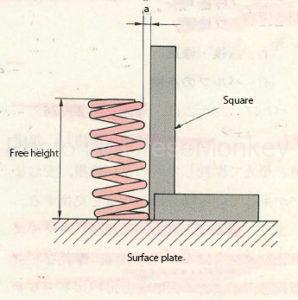
Figure 28: Spring squareness measurement
For the squareness of the spring, place the spring on a surface plate as shown in Fig. 28, apply a square to the spring tip and measure the dimensions (a) of the square, and replace it if it exceeds the specified value.
Inspection of valve seat ring
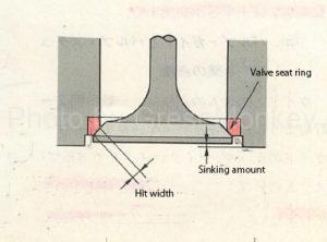
Figure 29: Valve contact width and sinking
The valve seat ring is inspected for scratches, dents, etc. on the contact surface with the valve face. Also, as shown in Fig. 29, check whether the contact width and contact position of the seat ring are appropriate for the valve face, and if there is a problem, polish or replace the seat ring.
Since the sinking of the seat ring increases with polishing, measure it with a caliper or the like, and if it exceeds the specified value, replace the seat ring.
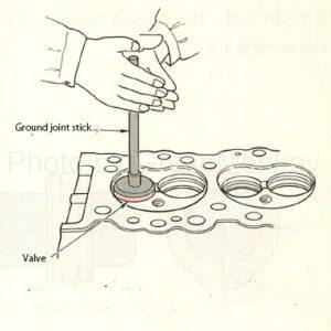
Figure 30: Alignment of valve face and valve seat ring
When replacing the valve or valve seat, finish the seat ring surface with a valve seat grinding machine, rub the seat ring against the valve face by the method shown in Fig. 30, and then apply Komeitan to the seat ring surface. , Tap the valve on the seat ring to check if the contact width is all around and if it is in the center of the valve face.
Inspection of rocker arm
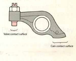
Figure 31: Rocker arm contact surface
For the rocker arm, inspect the contact surface with the valve and cam shown in Fig. 31, and repair or replace any stepped wear or scratches.
Also, inspect the sliding surface with the rocker shaft, measure its inner diameter with a caliper gauge, etc., and replace it if there is uneven wear or wear that exceeds the specified value.
Inspection of rocker shaft
For bending of the rocker shaft, support both ends with V blocks, measure with a dial gauge while turning the shaft, and replace the one that exceeds the specified value.
For wear, measure several points on the outer diameter and replace those that exceed the specified value.
Inspection of camshaft
For the camshaft, the height (H) of the cam and the diameter (D) of the cam base circle shown in Fig. 32 are measured at two points, H1 and H2, using a micrometer, and the difference is specified by the camlift (HD). If it is less than the value, replace it.
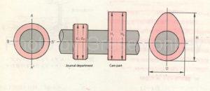
Figure 32: Camshaft wear measurement
Similarly, for the camshaft journal section, measure in the A-A’and B-B’directions at two points, d1 and d2, and replace the one that exceeds the specified value.
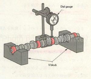
Figure 33: Camshaft runout measurement
As for the bending of the camshaft, as shown in Fig. 2-84, support both ends with the V block and apply a dial gauge to the journal part in the center to measure the runout.
If the camshaft is equipped with a drive gear such as a distributor, check for damage and wear on the tooth surface.
Inspection of camshaft bearings
The camshaft bearing is inspected for wear by measuring the inner diameter with a cylinder gauge. If the gap with the camshaft journal exceeds the limit, the bearing is replaced, but if the bearing is integrated with the cylinder head, the cylinder head is replaced.
Inspection of timing belt
Check the timing belt for cracks, wear, cracks, breakage, missing teeth, etc., and replace it if it is defective.
Timing chain inspection
Check the timing chain for wear and damage on the rollers, and replace any defective ones.
Key points of disassembling and assembling the valve mechanism
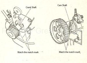
Figure 34: An example of a match mark
- If the camshaft bearing is made of white metal with a slush fund, be careful not to damage the bearing when removing the camshaft.
- When assembling the camshaft to the cylinder head, tighten the nuts of the camshaft bearing cap to the specified torque, and then check that the camshaft rotates lightly and that the axial play is within the specified value.
- When assembling a timing chain or timing belt, assemble so that the matching marks match as shown in Fig. 34. If the installation and adjustment method is specified, follow the specified procedure. After assembly, the valve clearance is adjusted. => Engine inspection and maintenance
- Be careful not to twist the timing belt, bend it strongly, turn it over, hang it around your neck, or allow it to get water or oil on it.
- When assembling the rocker arm, be careful because the shape for the inlet and the shape for the exhaust may be different. When assembling the rocker shaft assembly to the cylinder head, tighten it from the center with the specified torque.