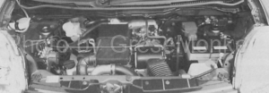
2006 Heisei Suzuki MR Wagon Model: DBA-MF22s Engine Model: K6A inline 3 cylinder 650 cc 12 valve DOHC

Many sensors used in automobiles are responsible for sensing some input of engine elements and signaling the actuators that control them. Therefore, there are only two troubles of each sensor, either not detecting the input correctly or sending the signal correctly.
The figure below shows the types and positional relationships of sensors that are adopted in the K6A engine of the Suzuki MR Wagon and the terminal arrangement of the engine control unit (ECU).
We introduce the actual measurement results of what kind of signals are output by the sensors used in the actual car and the waveforms observed by the oscilloscope.
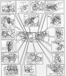
K6A engine of Suzuki MR Wagon and list of sensors used
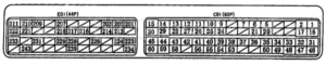
Terminal arrangement of K6A engine control unit (ECU)
Engine adjustment
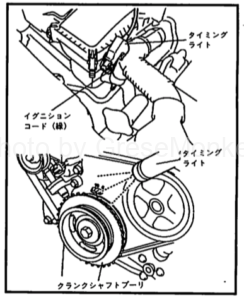
Inspection of ignition timing
Clamp the timing light to the ignition coil connection harness for No. 1 cylinder. (Lower figure) The reference value is 5 ± 3 ° BTDC / 900 ± 50 rpm, but can not be adjusted. After repairing the defective part, check again to see if it is at the reference value.
Inspection of idling speed
There is no place to install the tachometer, so check the engine speed with the maker dedicated tester. The reference value is 900 ± 50 rpm (N or P) at engine no load. (Unadjustable) Similarly check the defective part again for the reference value after repair.
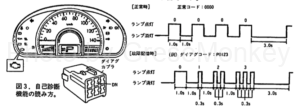
Self-diagnosis (Diagnosis)
By short-circuiting the DN terminal of the Diag Monitor Coupler (Milky White 6P) shown below with the IG switch ON, it can be read by the number of flashes of the onboard engine check lamp. The code is displayed in 4 digits, 0 is lighted for 1 second, otherwise it is lighted for 0.3 seconds, code is displayed for 3 seconds pause. For code erase, remove the DOME fuse for over 20 seconds. (Or, remove the minus terminal of the battery.) Actually, it was not possible to delete until about 60 seconds or more had elapsed.
Sensor signal output waveform
Below, we introduce the waveform of the real sensor’s oscilloscope. The numbers in parentheses are the numbers of the terminal arrangement diagram of the engine control unit (ECU).
Terminal arrangement diagram of engine control unit (ECU) of K6A type engine
Crank angle sensor signal (# 9) / cam angle sensor CS 2 signal (# 24)
Both of these sensors are of the magnetic type.
[Crank angle sensor actual measurement value]: 1.55 V at cranking, 1.44 V at idling, 1.38 V at 2500 rpm [Measurement value of cam angle sensor]: 1.14 V at cranking, 1.17 V at idling, 1.17 V at 2500 rpmFigure 1 below shows the output waveforms of the cam angle sensor (upper) and the crank angle sensor (lower) during idling. FIG. 2 shows the case at 2500 rpm.
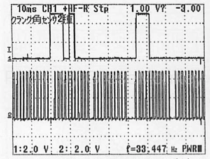
Output signal waveform of cam angle sensor (upper) and crank angle sensor (lower) during idling
Pressure sensor signal (# 58)
[Actual measurement value of intake air amount signal]: 4.01 V at IG ON, 1.42 V at idling, 1.29 V at 2000 rpm, 1.36 V at 4000 rpmFigure 3 shows the output waveform of the throttle sensor when IG OFF → IG ON → full accelerator → fully closed → IG OFF.
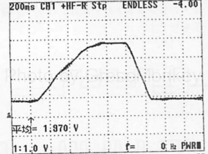
Output signal waveform of throttle sensor
Water temperature sensor signal (# 11)
[Water temperature sensor actual measurement value]: Pseudo coolant temperature 120 ° C: 0.32 V, as shown in the table below.| 100℃ | 80℃ | 60℃ | 40℃ | 20℃ | 0℃ |
| 0.42V | 0.78V | 1.24V | 1.94V | 2.87V | 3.80V |
Intake air temperature sensor signal (# 26)
[Measured value] Pseudo coolant temperature 120 ° C: 0.27 V or less As shown in the table.| 100℃ | 80℃ | 60℃ | 40℃ | 20℃ | 0℃ |
| 0.35V | 0.65V | 1.06V | 1.68V | 2.55V | 3.49V |
LAF sensor IPA signal (# 13)
Fig. 4 shows the output waveform of the LAF sensor IPA signal at 2500 rpm.
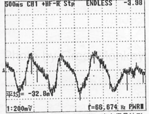
Figure 4: LAF sensor output signal waveform at 2500 rpm
Actuator (control system)
Fuel injection control (# 1, # 2, # 17)
In the fuel injection system, sequential injection is performed during cranking and idling, and simultaneous injection is performed during acceleration interruption.
[Actual Measurement] Cranking Injection Time: 11.8 sec, Operating Voltage: 11.27 V, Idling Injection Time: 2 msec, Operating Voltage: 14.09 V, 3000 rpm Injection Time: 2 msec, Operating Voltage: 13.94 V5 to 8 shown below are waveforms of output signals of the injectors in each state, in which (upper) is the injector NO1 and (lower) is the injector NO3.
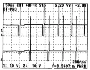
Figure 5: Cranking
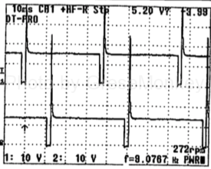
Figure 6: 3000 rpm
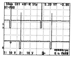
Figure 7: Idling
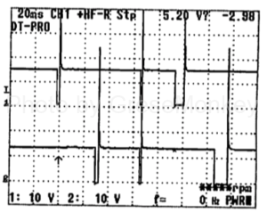
Figure 8: During rapid acceleration racing
Ignition timing control (# 34, # 35, # 36)
The distribution method is a direct method (ignition coil with built-in power transistor).
9 to 10 shown below show the waveforms of the ignition output signal 1 (upper) and the ignition output signal 2 (lower) at the time of idling and at 3000 rpm.
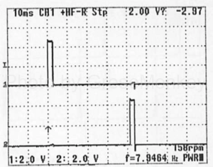
Figure 9: During idling
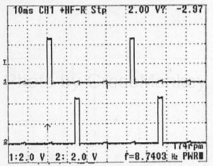
Figure 10: 3000 rpm
Idling speed control (SMA (# 5), SMB (# 6), SNC (# 20), SMD (# 21))
Idling rotation control by step motor type is performed.
The lower figure 11 shows the output waveforms of the SMA signal (upper) and the SMB signal (lower) during no load idling.
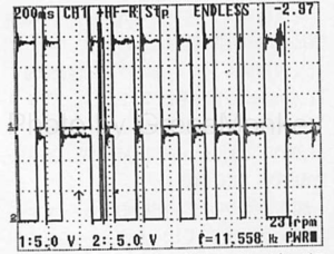
Fig. 11: Stepping motor type idling speed control signal at no load idling. SMA signal (upper), SMB signal (lower)
Variable valve timing of the intake side valve is varied by the oil control (OCV).
FIG. 12 shown below is the output waveform of the OCV signal immediately after the leave.
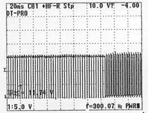
Fig. 12: Output signal waveform of oil control valve OCV during rapid acceleration