Suspension and tire ground contact
Suspensions are required to have a comfortable ride and excellent maneuvering stability, but among the elements necessary for vehicle design such as suspension geometry required for suspension design to realize these, design development It is perfect if the degree of freedom is high, the cost is low, and the space required for suspension installation in the vehicle is compact.
For example, the independent suspension has a high degree of freedom in design, and a lightweight unsprung load can provide a comfortable ride. In addition, since it meets the above-mentioned elements required for suspension geometry, it has been developed with an emphasis on improving steering stability.
Here, based on this suspension geometry, we will consider one of the important roles of the suspension system, how to properly install the tires on the road surface, focusing on the roll motion of the vehicle. ..
What is suspension geometry?
Suspension geometry (direction and force on suspension link, installation position, etc.). In other words, by considering this geometry, what kind of force is applied to the movable range of each part that constitutes the suspension due to the movement of the vehicle (movement of the tire), and in which direction it moves, as a result, the alignment of the vehicle And how the position and movement of the tires change. With that in mind, the alignment changes and tire steering angles when the vehicle moves should be optimized. It serves as a guideline for creating a plan to set the suspension link arrangement based on the behavior of the entire vehicle.
Considering vector analysis, the locus of the tire installation shop when the vehicle moves is obtained from this suspension geometry, and it is assumed that the momentary center of the suspension link is on the direction of any point on the locus. , Determines the lift dive action (vertical movement) of the vehicle body corresponding to the tire input (force applied to the tire).
Alternatively, to decompose the tire input into a vector in the direction of connecting the joint element of each suspension link to an arbitrary point, analyze the input applied to each suspension link, and calculate the strength of the suspension link and the support. Use.
The characteristic values to be analyzed for determining these factors are wheel alignment, kingpin tilt angle, offset, wheel center and ground contact position (tread, wheelbase), roll axis, lift dive geometry, and the like.
Table of Contents
- What is suspension geometry?
- Suspension and stroke
- For double wishbone
- How to find a roll center
- For double wishbone
- In the case of strut type
Suspension and stroke
In many suspension types, various measures have been taken to pursue how to properly install the tires on the road surface.
In general, it is considered ideal that the tire is in contact with the road surface almost perpendicularly in order to fully exert the performance of the tire. The tendency becomes stronger as the tire width becomes wider (the lower the profile). Rigid axles also perform excellently in keeping the tires perpendicular to the road surface.
For double wishbone
The basic form of double wishbone suspension is when the constituent suspension arms are parallel and of equal length. In this case, the inclination (angle) with respect to the vehicle body does not change even if the wheels move up and down, but the tread does change. (refer graph1)
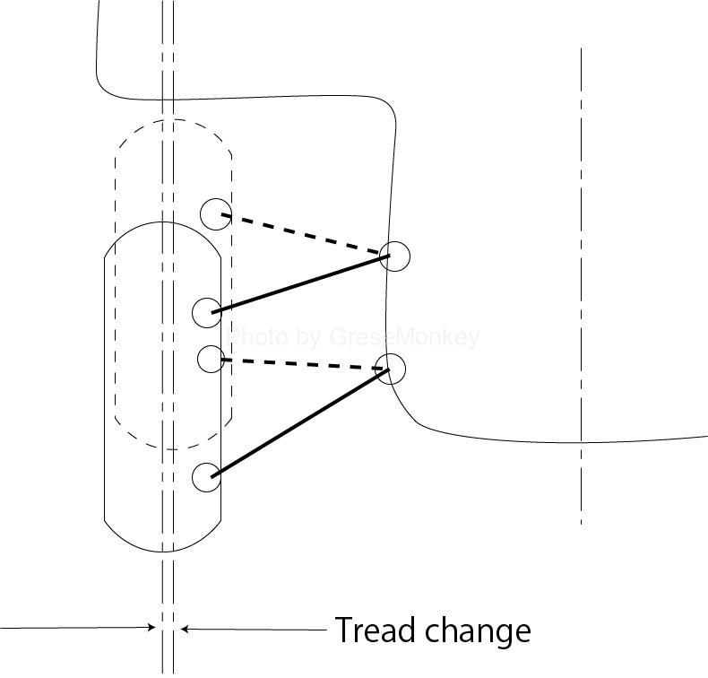
Figure 1: Tread change of isometric parallel arms
Since the change in the tread means that the ground contact point of the tire changes (scuff change), the unevenness of the road surface may cause the vehicle body to wobble.
In addition, when the vehicle body tilts due to the centrifugal force caused by cornering (roll), the tires also tilt at the same angle as the vehicle body, so they tilt diagonally to the road surface and touch the ground, reducing the cornering ability of the tires (cornering force). It will be. (See Fig. 2) (Cornering force: The force that causes the tire to move toward the inside of the corner against the centrifugal force during cornering, that is, the centripetal force)
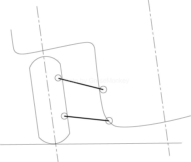
Figure 2: Tire strength when rolled
Therefore, in reality, the upper suspension arm is shortened, and the upper and lower suspension arms are attached at an angle instead of parallel, so that the tread and the angle of the tire with respect to the road surface do not change as much as possible. .. (See Figure 3)
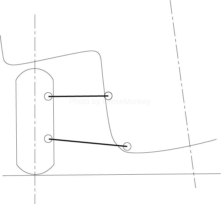
Figure 3: In the case of unequal length parallel arms
However, this method has the weakness that if the left and right wheels stroke in the same way at the same time, such as when braking or over a step, the tires of both wheels tilt inward as if writing a letter “H” when viewed from the front of the vehicle.
In other words, when the suspension strokes, it causes the vehicle body to shake such as rolling and pitching, and changes in wheel alignment, which causes troubles. From the viewpoint of steering stability, it is desirable that the suspension does not stroke as much as possible. Therefore, in sports cars and high-performance cars of the same model, the springs are stiffened and the suspension is stiffened as much as possible.
The movement of the wheels changes variously depending on the length and mounting position of the suspension arm, but the movement of the suspension is naturally determined by the dimensions and mounting position of the parts constituting the suspension such as the suspension arm.
That is, depending on the geometrical requirements such as the length of the suspension arm and the mounting position, how the alignment such as the camber of the tire changes when the suspension strokes changes.
Therefore, this geometrical arrangement of the suspension arm and the like is called suspension geometry, and is an important factor for determining the inclination and position of the tire when the suspension strokes.
In another sense, it can also be used as a general term that includes items that are important considerations when examining suspension geometry, such as wheel alignment changes and roll center positions that are determined by this geometric arrangement. be.
Here, the roll center is the central position when the vehicle body rolls in cornering, but this has a great effect on the movement of the wheels when the suspension strokes, and by extension, the characteristics of the vehicle when cornering. To exert. Therefore, where to place the roll center is an important point in the suspension geometry.
Other suspension geometry is an important design requirement that affects suspension characteristics and vehicle performance because it also affects changes in vehicle attitude such as the rear part of the vehicle lowering when accelerating and leaning forward when braking.
How to find a roll center
For double wishbone

Figure 4: Double wishbone geometry
Suppose there is a double wishbone suspension as shown in Fig. 4 when viewed from the front of the vehicle. The attachment point on the vehicle body side of the upper arm is A, the connection point on the hub carrier (axle housing) side (joint part such as a ball joint) is B, the attachment point on the vehicle body side of the lower arm is C, and the connection point on the hub carrier side is Let it be D.
Then, when the suspension strokes, point B will rotate around point A, but the direction of movement of point B will momentarily move in the direction perpendicular to the upper arm AB. Similarly, point D moves in the direction perpendicular to the lower arm CD.
Therefore, the hub carrier as a whole will rotate around the intersection O of the straight lines extending the upper arm AB and the lower arm CD, respectively. The point O is called the momentary center or the momentary rotation center as the momentary center where the wheel moves. The reason for calling it the momentary center is that the position of point O moves as the suspension strokes.
The length from the momentary center O to the tire contact patch P (center of the contact patch) is called the swing arm length. In other words, at the grounding point P, consider that the virtual swing arm OP rotates around the instantaneous center O.
Therefore, the movement of the ground contact point P of the tire depends on the height of the instantaneous center O and the length of the swing arm. That is, when the position of the instantaneous center O is high, the tread change, which is the lateral movement of the ground contact point P, becomes large when the suspension strokes, and the camber change becomes gentle as the swing arm length becomes long. (See Figure 5)
This is an important point when considering suspension geometry.
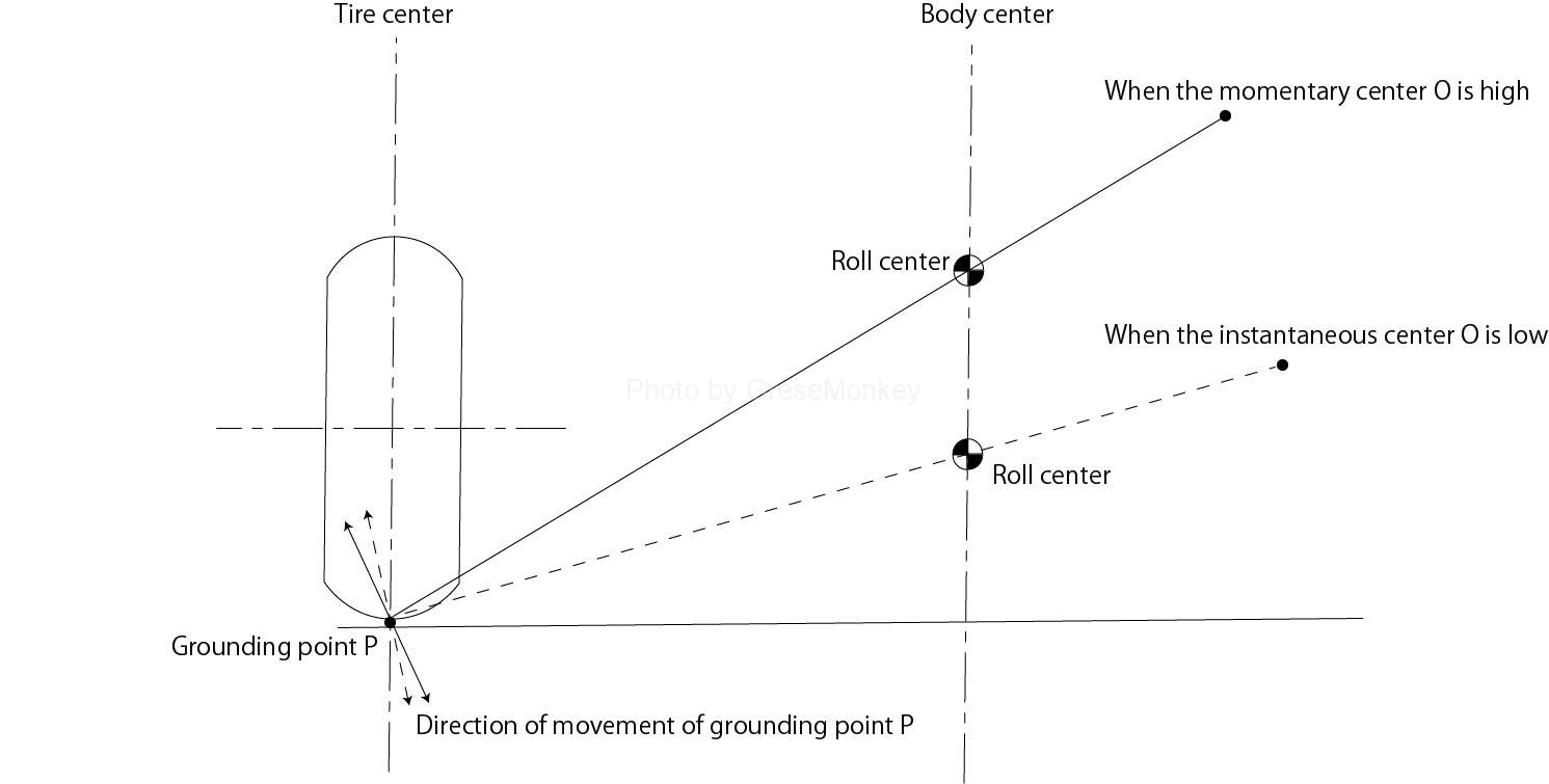
Figure 5: Effect of instantaneous center height and swing arm length
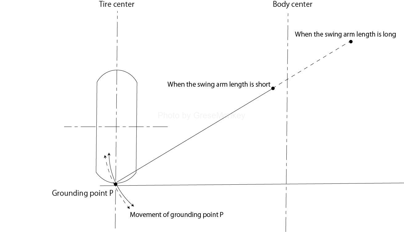
Figure 5: Effect of instantaneous center height and swing arm length
In FIG. 6, the momentary centers of the left and right wheels are obtained, and the momentary centers O of the left and right wheels are connected to the ground contact point P. Then, at this moment, the point where the two straight lines connecting the center O and the grounding point P intersect is the desired roll center. (Fig. 6)
reference)
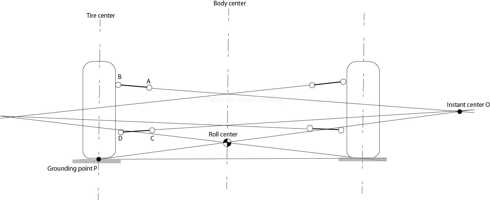
Figure 6: Double wishbone roll center
If the strokes of the left and right suspensions are the same, the roll center coincides with the point where the straight line connecting the momentary center and the ground contact point P intersects the center line of the vehicle body.
From the above points, it can be seen that the positions of the momentary center and the roll center can be freely selected depending on the mounting positions of the upper and lower suspension arms. And this is a big feature of the double wishbone system.
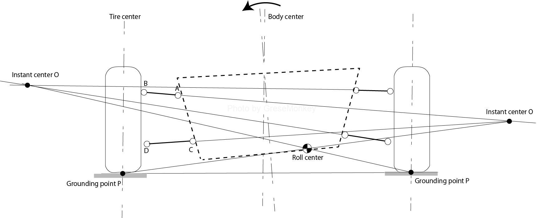
Figure 7: Roll center movement when rolling
For example, when the vehicle body rolls and one wheel makes a bound (bump) stroke and the other wheel makes a rebound stroke, the roll center moves significantly. (See Figure 7)
However, unless it is examined in detail, in general, it is often the case that the position of the roll center is set based on the state where neither the left or right wheel is bound or rebounded.
In the case of strut type
The strut type is a combination of a lower arm and a strut, but since the strut moves linearly, it can be considered by replacing it with a near infinite upper arm. That is, when a straight line is extended at right angles to the piston rod from the attachment point B on the vehicle body side of the strut, the intersection with the extension line of the lower arm CD becomes the instantaneous center O. (See Figure 8)
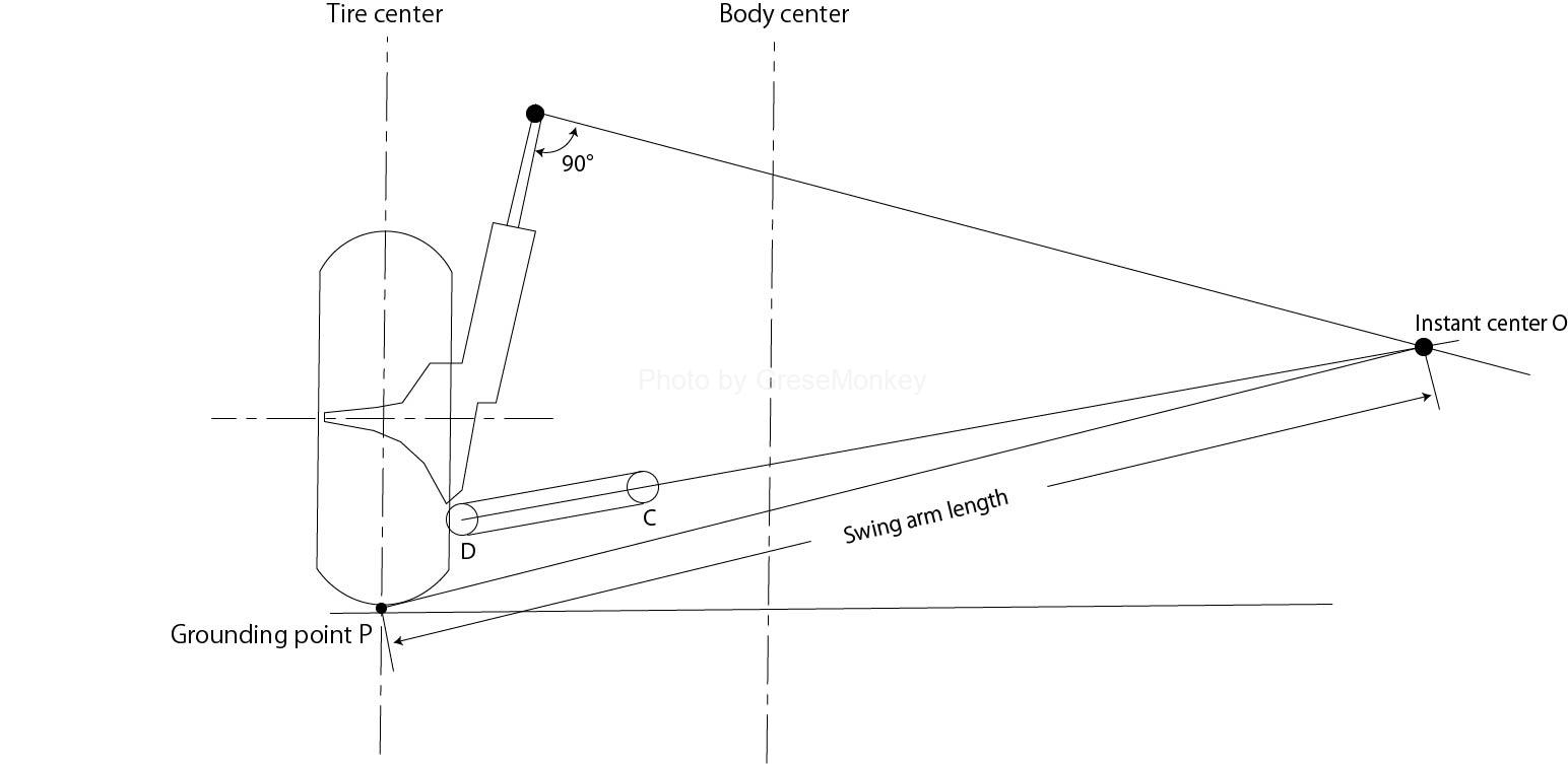
Figure 8: Strut geometry
At this time, the straight line extends at a right angle to the piston rod, and the piston rod does not coincide with the virtual kingpin axis connecting the attachment point B on the vehicle body side of the strut and the connection point D with the lower arm.
Therefore, when considering the future from here, the same as in the case of the double wishbone system, find the momentary center of both the left and right wheels, and connect the momentary center O and the grounding point P of each of the left and right wheels. The intersection of these two straight lines is the roll center. (See Figure 9)
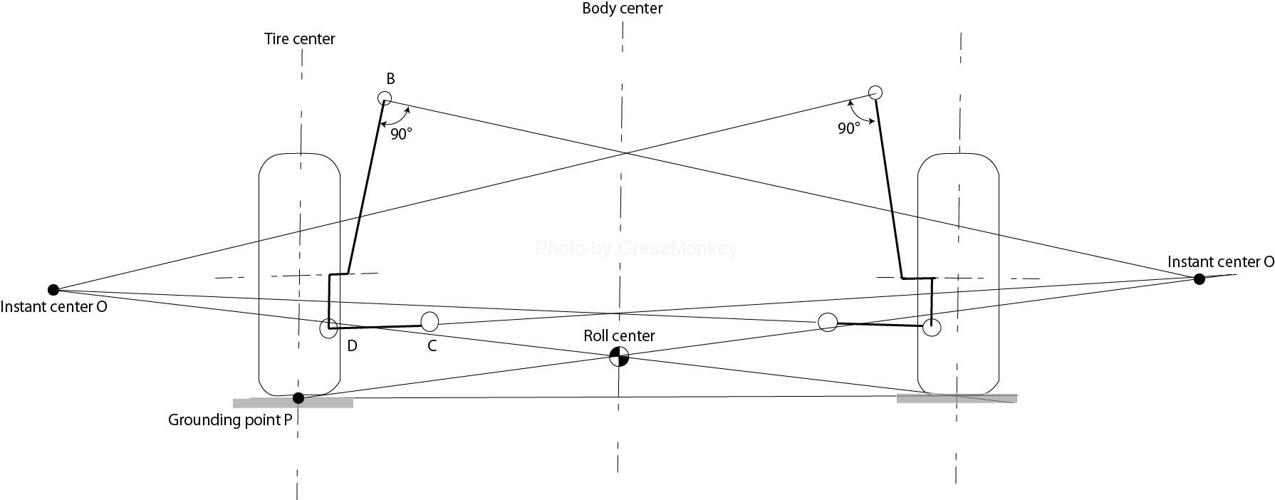
Figure 9: Strut-type roll center
Further, if the strokes of the left and right suspensions are the same, the straight line connecting the instantaneous center O and the ground contact point P may be a point where the center line of the vehicle body intersects.
Here, even if the geometry is changed to move the position of the instantaneous center or the roll center, the position of the lower arm is restricted by the position of the hub carrier and the requirement of the minimum ground clearance. Also, even if you try to shorten the length of the swing arm and tilt the attachment point on the vehicle body side of the strut inward, it will affect the size of the engine room, so the length will be decided naturally.
In other words, the strut type has a small number of parts and a simple structure, but has the disadvantage of reducing the degree of freedom in design.